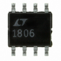
LT1806CS8 Linear Technology, LT1806CS8 Datasheet - Page 21

LT1806CS8
Manufacturer Part Number
LT1806CS8
Description
IC OPAMP R-R IN/OUT SNGL 8-SOIC
Manufacturer
Linear Technology
Datasheet
1.LT1806CS8PBF.pdf
(28 pages)
Specifications of LT1806CS8
Amplifier Type
General Purpose
Number Of Circuits
1
Output Type
Rail-to-Rail
Slew Rate
140 V/µs
Gain Bandwidth Product
325MHz
Current - Input Bias
5µA
Voltage - Input Offset
100µV
Current - Supply
11mA
Current - Output / Channel
85mA
Voltage - Supply, Single/dual (±)
2.5 V ~ 12.6 V, ±1.25 V ~ 6.3 V
Operating Temperature
0°C ~ 70°C
Mounting Type
Surface Mount
Package / Case
8-SOIC (3.9mm Width)
Lead Free Status / RoHS Status
Contains lead / RoHS non-compliant
-3db Bandwidth
-
Available stocks
Company
Part Number
Manufacturer
Quantity
Price
Part Number:
LT1806CS8
Manufacturer:
LINEAR/凌特
Quantity:
20 000
Company:
Part Number:
LT1806CS8#PBF
Manufacturer:
LT
Quantity:
1 469
Part Number:
LT1806CS8#PBF
Manufacturer:
LT
Quantity:
20 000
Part Number:
LT1806CS8#TRPBF
Manufacturer:
LINEAR/凌特
Quantity:
20 000
TYPICAL APPLICATIONS
Driving A/D Converter
The LT1806/LT1807 have 60ns settling time to 0.01% on
a 2V step signal, and 20Ω output impedance at 100MHz,
that makes them ideal for driving high speed A/D convert-
ers. With the rail-to-rail input and output, and low supply
voltage operation, the LT1806/LT1807 are also desirable
for single supply applications. As shown in the application
on the front page of this data sheet, the LT1807 drives a
10Msps, 12-bit, LTC1420 ADC in a gain of 20. Driving the
LTC1420 differentially will optimize the signal-to-noise
ratio, SNR, and the total harmonic distortion, THD, of the
A/D converter. The lowpass fi lter, R5, R6 and C3 reduce
1.5V
V
P-P
IN
R1
1k
+
–
LT1806
–5V
5V
Figure 2. Noninverting A/D Driver
R2
1k
49.9Ω
R3
C1
470pF
+A
–A
IN
IN
PGA GAIN = 1
REF = 2.048V
LTC1420
–5V
5V
18067 F02
•
•
•
12 BITS
10Msps
noise or distortion products that might come from the input
signal. High quality capacitors and resistors, NPO chip
capacitor and metal fi lm surface mount resistors, should
be used since these components can add to distortion.
The voltage glitch of the converter, due to its sampling
nature is buffered by the LT1807, and the ability of the
amplifi er to settle it quickly will affect the spurious free
dynamic range of the system. Figure 2 depicts the LT1806
driving LTC1420 at noninverting gain of 2 confi guration.
The FFT responses show a better than 92dB of spurious
free dynamic range, SFDR.
–100
–120
–20
–40
–60
–80
Figure 3. 4096 Point FFT Response
0
0
1
FREQUENCY (MHz)
LT1806/LT1807
2
V
A
f
f
SFDR = 92.5dB
3
SAMPLE
IN
S
V
= 5V
= 2
= 1.4086MHz
= 10Msps
4
18067 F03
5
21
18067fc


