LT1210CT7 Linear Technology, LT1210CT7 Datasheet - Page 9
LT1210CT7
Manufacturer Part Number
LT1210CT7
Description
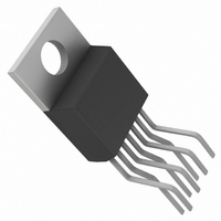
IC AMP C-FEEDBACK 1.1A TO-220-7
Manufacturer
Linear Technology
Datasheet
1.LT1210CT7PBF.pdf
(16 pages)
Specifications of LT1210CT7
Amplifier Type
Current Feedback
Number Of Circuits
1
Slew Rate
90 V/µs
-3db Bandwidth
55MHz
Current - Input Bias
10µA
Voltage - Input Offset
3000µV
Current - Supply
35mA
Current - Output / Channel
2A
Voltage - Supply, Single/dual (±)
10 V ~ 30 V, ±5 V ~ 15 V
Operating Temperature
0°C ~ 70°C
Mounting Type
Through Hole
Package / Case
TO-220-7 (Bent and Staggered Leads)
Lead Free Status / RoHS Status
Contains lead / RoHS non-compliant
Output Type
-
Gain Bandwidth Product
-
Available stocks
Company
Part Number
Manufacturer
Quantity
Price

Company:
Part Number:
LT1210CT7
Manufacturer:
XI;
Quantity:
5 510
Part Number:
LT1210CT7
Manufacturer:
LT
Quantity:
20 000
Part Number:
LT1210CT7#06PBF
Manufacturer:
LINEAR/凌特
Quantity:
20 000
Part Number:
LT1210CT7#37PBF
Manufacturer:
LINEAR/凌特
Quantity:
20 000
Part Number:
LT1210CT7#44PBF
Manufacturer:
LINEAR/凌特
Quantity:
20 000
Company:
Part Number:
LT1210CT7#PBF
Manufacturer:
LINEAR
Quantity:
1 250
Part Number:
LT1210CT7#PBF
Manufacturer:
LINEAR/凌特
Quantity:
20 000


up the turn-off time and ensures that the LT1210 is
completely turned off. Because the pin is referenced to
the positive supply, the logic used should have a break-
down voltage of greater than the positive supply voltage.
No other circuitry is necessary as the internal circuit
limits the Shutdown pin current to about 500µA. Figure
3 shows the resulting waveforms.
A
For applications where the full bandwidth of the amplifier
is not required, the quiescent current of the device may be
reduced by connecting a resistor from the Shutdown pin
to ground. The quiescent current will be approximately 65
times the current in the Shutdown pin. The voltage across
the resistor in this condition is V
82k resistor will set the quiescent supply current to 9mA
with V
The photos in Figures 4a and 4b show the effect of
reducing the quiescent supply current on the large-signal
PPLICATI
S
= ±15V.
ENABLE
A
R
R
V
F
L
= 1
= 825Ω
= 50Ω
Figure 3. Shutdown Operation
Figure 2. Shutdown Interface
O
V
5V
IN
74C906
U
R
V
V
PULL-UP
IN
S
= ±15V
= 1V
S
+
–
P-P
LT1210
= 24k
SD
I FOR ATIO
U
15V
24k
–15V
+
– 3V
15V
W
BE
. For example, a
R
R
F
G
1210 F03
1210 F02
V
OUT
U
response. The quiescent current can be reduced to 9mA in
the inverting configuration without much change in re-
sponse. In noninverting mode, however, the slew rate is
reduced as the quiescent current is reduced.
Slew Rate
Unlike a traditional op amp, the slew rate of a current
feedback amplifier is not independent of the amplifier gain
configuration. There are slew rate limitations in both the
input stage and the output stage. In the inverting mode,
and for higher gains in the noninverting mode, the signal
amplitude on the input pins is small and the overall slew
rate is that of the output stage. The input stage slew rate
is related to the quiescent current and will be reduced as
the supply current is reduced. The output slew rate is set
by the value of the feedback resistors and the internal
capacitance. Larger feedback resistors will reduce the
slew rate as will lower supply voltages, similar to the way
Figure 4a. Large-Signal Response vs I
Figure 4b. Large-Signal Response vs I
R
R
R
R
F
L
F
L
= 750Ω
= 10Ω
= 750Ω
= 10Ω
I
V
I
V
Q
Q
S
S
= 9mA, 18mA, 36mA
= 9mA, 18mA, 36mA
= ±15V
= ±15V
Q
Q
, A
, A
1210 F04b
1210 F04a
V
V
LT1210
= –1
= 2
1210fa
9
Related parts for LT1210CT7
Image
Part Number
Description
Manufacturer
Datasheet
Request
R

Part Number:
Description:
1.1A/ 35MHz Current Feedback Amplifier
Manufacturer:
Linear Technology
Datasheet:
Part Number:
Description:
CD ROM LINEARVIEW DATASHEETS
Manufacturer:
Linear Technology

Part Number:
Description:
Standalone Linear Li-Ion Battery Charger with Thermal Regulation in ThinSOT
Manufacturer:
Linear Technology Corporation
Datasheet:
Part Number:
Description:
Low noise, high frequency, 8th order linear phase lowpass filter
Manufacturer:
Linear Technology Corporation
Datasheet:
Part Number:
Description:
Manufacturer:
Linear Technology Corporation
Datasheet:
Part Number:
Description:
Manufacturer:
Linear Technology Corporation
Datasheet:
Part Number:
Description:
Manufacturer:
Linear Technology Corporation
Datasheet:
Part Number:
Description:
Manufacturer:
Linear Technology Corporation
Datasheet:
Part Number:
Description:
Manufacturer:
Linear Technology Corporation
Datasheet:
Part Number:
Description:
Manufacturer:
Linear Technology Corporation
Datasheet:
Part Number:
Description:
Manufacturer:
Linear Technology Corporation
Datasheet:
Part Number:
Description:
Dual and Quad, JFET Input Precision High Speed Op Amps
Manufacturer:
Linear Technology Corporation
Datasheet:
Part Number:
Description:
Manufacturer:
Linear Technology Corporation
Datasheet:
Part Number:
Description:
1, 2, 6 and 8 Channel, 10-Bit Serial I/O Data Acquisition Systems
Manufacturer:
Linear Technology Corporation
Datasheet:
Part Number:
Description:
Manufacturer:
Linear Technology Corporation
Datasheet: