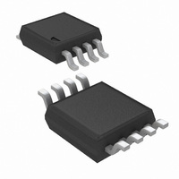
LMP8602MMX/NOPB National Semiconductor, LMP8602MMX/NOPB Datasheet - Page 16

LMP8602MMX/NOPB
Manufacturer Part Number
LMP8602MMX/NOPB
Description
IC AMP CURRENT SENSE 60V 8-MSOP
Manufacturer
National Semiconductor
Series
LMP®r
Datasheet
1.LMP8602MMENOPB.pdf
(24 pages)
Specifications of LMP8602MMX/NOPB
Amplifier Type
Current Sense
Number Of Circuits
1
Slew Rate
0.83 V/µs
Gain Bandwidth Product
60kHz
Current - Input Bias
0.04pA
Voltage - Input Offset
150µV
Current - Supply
1.1mA
Current - Output / Channel
48mA
Voltage - Supply, Single/dual (±)
3 V ~ 5.5 V
Operating Temperature
-40°C ~ 125°C
Mounting Type
Surface Mount
Package / Case
8-MSOP, Micro8™, 8-uMAX, 8-uSOP,
Lead Free Status / RoHS Status
Lead free / RoHS Compliant
Output Type
-
-3db Bandwidth
-
Other names
LMP8602MMX
www.national.com
R
first step of the design procedure with the following equation:
For the gain of 5 for the LMP8602 this results in:
For the gain of 10 for the LMP8603 this is:
For instance, the value of Q can be set to 0.5
Butterworth response, to 1/
or a 0.5 to create a critically damped response. Once the
value of R
design procedure is to calculate the required value of C to give
the desired low-pass cut-off frequency using:
Which for the gain = 5 will give:
and for the gain = 10:
2
can be calculated based on the desired value of Q as the
2
has been found, the second and last step of the
√
3 to create a Bessel response,
FIGURE 3. Reduce Gain for Unidirectional Application
√
2 to create a
16
For C
Or for a gain = 5:
and for a gain = 10:
Note that the frequency response achieved using this proce-
dure will only be accurate if the cut-off frequency of the second
order filter is much smaller than the intrinsic 60 kHz low-pass
filter. In other words, to have the frequency response of the
LMP8602/LMP8602Q/LMP8603/LMP8603Q circuit chosen
such that the internal poles do not affect the external second
order filter.
For a desired Q = 0.707 and a cut off frequency = 3 kHz, this
will result for the LMP8602 in rounded values for R2 = 51
kΩ, C1 = 1.5 nF and C2 = 3.9 nF
And for the LMP8603 this will result in rounded values for R2
= 22 kΩ, C1 = 3.3 nF and C2 = 0.39 nF
GAIN ADJUSTMENT
The gain of the LMP8602 is 50 and the gain of the LMP8603
is 100, however, this gain can be adjusted as the signal path
in between the two internal amplifiers is available on the ex-
ternal pins.
Reduce Gain
Figure 3
the gain of the LMP8602 and the LMP8603 in unidirectional
sensing applications.
2
the value is calculated with:
shows the configuration that can be used to reduce
30083456


