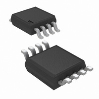
LMP8602MMX/NOPB National Semiconductor, LMP8602MMX/NOPB Datasheet - Page 19

LMP8602MMX/NOPB
Manufacturer Part Number
LMP8602MMX/NOPB
Description
IC AMP CURRENT SENSE 60V 8-MSOP
Manufacturer
National Semiconductor
Series
LMP®r
Datasheet
1.LMP8602MMENOPB.pdf
(24 pages)
Specifications of LMP8602MMX/NOPB
Amplifier Type
Current Sense
Number Of Circuits
1
Slew Rate
0.83 V/µs
Gain Bandwidth Product
60kHz
Current - Input Bias
0.04pA
Voltage - Input Offset
150µV
Current - Supply
1.1mA
Current - Output / Channel
48mA
Voltage - Supply, Single/dual (±)
3 V ~ 5.5 V
Operating Temperature
-40°C ~ 125°C
Mounting Type
Surface Mount
Package / Case
8-MSOP, Micro8™, 8-uMAX, 8-uSOP,
Lead Free Status / RoHS Status
Lead free / RoHS Compliant
Output Type
-
-3db Bandwidth
-
Other names
LMP8602MMX
These figures can be used to estimate the disturbance that
will be caused when driving a switched capacitive load. To
minimize the error signal introduced by the sampling that oc-
curs on the ADC input, an additional RC filter can be placed
in between the LMP8602/LMP8602Q/LMP8603/LMP8603Q
and the ADC as illustrated in
The external capacitor absorbs the charge that flows when
the ADC sampling capacitor is connected. The external ca-
pacitor should be much larger than the sample and hold
capacitor at the input of the ADC and the RC time constant of
the external filter should be such that the speed of the system
is not affected.
LOW SIDE CURRENT SENSING APPLICATION WITH
LARGE COMMON MODE TRANSIENTS
Figure 10
with a low side driver. The power transistor is pulse width
FIGURE 9. Reduce Error When Driving ADCs
illustrates a low side current sensing application
FIGURE 10. Low Side Current Sensing Application with Large Common Mode Transients
Figure
9.
30083461
19
modulated to control the average current flowing through the
inductive load which is connected to a relatively high battery
voltage. The current through the load is measured across a
shunt resistor R
transistor is on, current flows from the battery through the in-
ductive load, the shunt resistor and the power transistor to
ground. In this case, the common mode voltage on the shunt
is close to ground. When the power transistor is off, current
flows through the inductive load, through the shunt resistor
and through the freewheeling diode. In this case the common
mode voltage on the shunt is at least one diode voltage drop
above the battery voltage. Therefore, in this application the
common mode voltage on the shunt is varying between a
large positive voltage and a relatively low voltage. Because
the large common mode voltage range of the LMP8602/
LMP8603 and because of the high AC common mode rejec-
tion ratio, the LMP8602/LMP8603 is very well suited for this
application.
For this application the following example can be used for the
calculation of the output signal:
When using a sense resistor, R
of 1A, then the output voltage at the input pins of the LMP8602
is: R
With the gain of 50 for the LMP8602 this will give an output of
0.5V. Or in other words, V
For the LMP8603 the calculation is similar, but with a gain of
100, giving an output of 1 V/A.
SENSE
* I
LOAD
SENSE
= 0.01 Ω * 1A = 0.01V
in series with the load. When the power
OUT
= 0.5V/A.
SENSE
, of 0.01 Ω and a current
30083452
www.national.com


