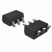
DVIULC6-4SC6 STMicroelectronics, DVIULC6-4SC6 Datasheet - Page 8

DVIULC6-4SC6
Manufacturer Part Number
DVIULC6-4SC6
Description
IC ESD PROTECTION LO CAP SOT23-6
Manufacturer
STMicroelectronics
Datasheet
1.DVIULC6-4SC6.pdf
(12 pages)
Specifications of DVIULC6-4SC6
Voltage - Reverse Standoff (typ)
5V
Voltage - Breakdown
6V
Polarization
4 Channel Array - Bidirectional
Mounting Type
Surface Mount
Package / Case
SOT-23-6
Applications
General Purpose
Number Of Circuits
4
Voltage - Working
6V
Voltage - Clamping
12V
Technology
Diode Array
Polarity
Bidirectional
Channels
4 Channels
Breakdown Voltage
6 V
Termination Style
SMD/SMT
Capacitance
1 pF
Dimensions
1.75 mm W x 3.05 mm L x 1.3 mm H
Diode Type
Low Capacitance / ESD Protection
Clamping Voltage Vc Max
17V
Diode Case Style
SOT-23
No. Of Pins
6
Lead Free Status / RoHS Status
Lead free / RoHS Compliant
Power (watts)
-
Lead Free Status / Rohs Status
Lead free / RoHS Compliant
Other names
497-5237-2
Available stocks
Company
Part Number
Manufacturer
Quantity
Price
Company:
Part Number:
DVIULC6-4SC6
Manufacturer:
ST
Quantity:
30 000
Part Number:
DVIULC6-4SC6
Manufacturer:
ST
Quantity:
20 000
Technical information
8/12
Figure 13. PCB layout considerations (V
It’s often harder to connect the power supply near to the DVIULC6-4SC6 unlike the ground
thanks to the ground plane that allows a short connection.
To ensure the same efficiency for positive surges when the connections can’t be short
enough, we recommend to put close to the DVIULC6-4SC6, between V
capacitance of 100 nF to prevent from these kinds of overfatigue disturbances (see
Figure 12
The addition of this capacitance will allow a better protection by providing a constant voltage
during a surge.
Figure
the recommendations described in
Figure 14. ESD behavior: measurement conditions (with coupling capacitor)
IMPORTANT:
An important precaution to take is to put the protection device as close as possible to the
disturbance source (generally the connector).
14,
and
Connector
Figure
Side
DVI
Figure
6, and
SURGE
ESD
13).
Figure 7
GND
Doc ID 11599 Rev 2
D+2
D+1
D-2
D-1
show the improvement of the ESD protection according to
Section
TEST BOARD
1
DVIULC6-4SC6
3.3.
CC
connection is application dependent)
C=100 nF
V cc (+5V)
BUS
C = 100nF
DVIULC6-4SC6
and ground, a
V
CC


