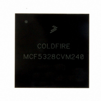
MCF5328CVM240 Freescale Semiconductor, MCF5328CVM240 Datasheet - Page 43

MCF5328CVM240
Manufacturer Part Number
MCF5328CVM240
Description
IC MCU 32BIT 240MHZ 256-MAPBGA
Manufacturer
Freescale Semiconductor
Series
MCF532xr
Datasheet
1.MCF5328CVM240J.pdf
(50 pages)
Specifications of MCF5328CVM240
Core Processor
Coldfire V3
Core Size
32-Bit
Speed
240MHz
Connectivity
EBI/EMI, Ethernet, I²C, SPI, SSI, UART/USART, USB, USB OTG
Peripherals
DMA, LCD, PWM, WDT
Number Of I /o
94
Program Memory Type
ROMless
Ram Size
32K x 8
Voltage - Supply (vcc/vdd)
1.4 V ~ 3.6 V
Oscillator Type
External
Operating Temperature
-40°C ~ 85°C
Package / Case
256-MAPBGA
Program Memory Size
16KB
Cpu Speed
240MHz
Embedded Interface Type
CAN, I2C, MAC, Ethernet, QSPI, UART
Rohs Compliant
Yes
Family Name
MPC5xxx
Device Core
ColdFire
Device Core Size
32b
Frequency (max)
240MHz
Instruction Set Architecture
RISC
Supply Voltage 1 (typ)
1.8/2.5/3.3V
Operating Supply Voltage (max)
1.6/1.95/2.75/3.6V
Operating Supply Voltage (min)
1.4/1.7/2.25/3V
Operating Temp Range
-40C to 85C
Operating Temperature Classification
Industrial
Mounting
Surface Mount
Pin Count
256
Package Type
MA-BGA
Lead Free Status / RoHS Status
Lead free / RoHS Compliant
Eeprom Size
-
Program Memory Size
-
Data Converters
-
Lead Free Status / Rohs Status
Compliant
Available stocks
Company
Part Number
Manufacturer
Quantity
Price
Company:
Part Number:
MCF5328CVM240
Manufacturer:
FREESCAL
Quantity:
717
Company:
Part Number:
MCF5328CVM240
Manufacturer:
Freescale Semiconductor
Quantity:
10 000
Part Number:
MCF5328CVM240
Manufacturer:
FREESCALE
Quantity:
20 000
Company:
Part Number:
MCF5328CVM240J
Manufacturer:
Freescale Semiconductor
Quantity:
10 000
Freescale Semiconductor
1
2
3
4
5
Stop Mode 3 (Stop 11)
Stop Mode 2 (Stop 10)
Stop Mode 0 (Stop 00)
Stop Mode 1(Stop 01)
All values are measured with a 3.30V EV
temperature with pins configured for high drive strength.
Refer to the Power Management chapter in the MCF532x Reference Manual for more information on low-power
modes.
All peripheral clocks except UART0, FlexBus, INTC0, reset controller, PLL, and edge port off before entering low
power mode. All code executed from flash.
All peripheral clocks on before entering low power mode. All code is executed from flash.
See the description of the low-power control register (LCPR) in the MCF532x Reference Manual for more
information on stop modes 0–3.
Wait/Doze
Mode
Run
450
400
350
300
250
200
150
100
50
0
58
4
5
4
4
Table 31. Current Consumption in Low-Power Modes
Figure 34. Current Consumption in Low-Power Modes
Voltage
MCF532x ColdFire
3.3 V
1.5 V
3.3 V
1.5 V
3.3 V
1.5 V
3.3 V
1.5 V
3.3 V
1.5 V
3.3 V
1.5 V
64
58 MHz
(Typ)
15.28
21.65
15.47
22.49
26.79
33.61
1.04
4.69
2.69
4.72
56.3
fsys/3 (MHz)
3.9
DD
, 3.30V SDV
3
72
®
Microprocessor Data Sheet, Rev. 5
64 MHz
(Typ)
16.44
21.68
16.63
22.52
28.85
33.61
3.92
1.04
4.72
2.69
4.73
60.7
DD
80
3
and 1.5V IV
80(peak)
72 MHz
(Typ)
17.85
24.33
18.06
25.21
30.81
1.04
2.70
4.81
42.3
65.4
4.0
4.8
DD
3
power supplies. Tests performed at room
80 MHz
(Typ)
19.91
26.13
20.12
27.03
34.47
1.04
2.70
4.81
50.5
73.4
4.0
4.8
1,2
Stop 0 - Flash
Stop 1 - Flash
Stop 2 - Flash
Stop 3 - Flash
Wait/Doze - Flash
Run - Flash
3
80 MHz
(Peak)
Current Consumption
20.42
26.16
20.67
132.3
1.08
2.75
4.81
39.8
97.4
62.6
4.8
4.0
4
Units
mA
43


