GS-BT2416C2DB STMicroelectronics, GS-BT2416C2DB Datasheet
GS-BT2416C2DB
Specifications of GS-BT2416C2DB


Related parts for GS-BT2416C2DB


GS-BT2416C2DB Summary of contents
Page 1
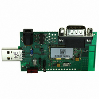
... The GS-BT2416C2DBAT1 is a board with downloaded FW which enables the user to create a Bluetooth link with simple AT commands. AT commands are sent by means of the serial line which is accessible by the DB9 connector. The GS-BT2416C2DB.xxx board can be supplied by an external source or via the USB port. Features ● ...
Page 2
Contents Contents 1 Recommended operating conditions . . . . . . . . . . . . . . . . . . . . . . . . . . . 3 2 I/O connections . . . ...
Page 3
UM0472 1 Recommended operating conditions Table 1. Recommended operating conditions Symbol VDD Board supply voltage Tstg Operating ambient temperature 2 I/O connections Table 2. Board connections 1 Boot signal - If connected to GND, the module can download – see ...
Page 4
I/O connections Table 2. Board connections (continued) Boot JP1 If connected to GND the module can download JP2 DB9 connector connection – see JP3 DB9 connector connection – see JP4 DB9 connector connection – see JP5 DB9 connector connection – ...
Page 5
UM0472 3 Board layout Figure 2. Board component layout Board layout 5/19 ...
Page 6
Board schematic 4 Board schematic Figure 3. Board schematic 6/19 SPI_FRM 17 SPI_CLK 18 SPI_TXD RF-GND 19 45 SPI_RXD ANT 20 44 USB_DN RF-GND 21 43 USB_DP 22 RESET 23 BOOT 24 UM0472 ...
Page 7
... UM0472 5 Downloading The user has the possibility to download his own file to the GS-BT2416C2DB: ● connect the board using an RS232 cable connected to COM1 / COM2 ● put a jumper on JP1 (Boot pin to low level) ● connect the power supply cable to the board ext Vin ● ...
Page 8
Certifications 6 Certifications 6.1 CE Measurements have been performed in accordance with (report available on request): ● EN 300 328 V 1.6.1 (2004-11): "Electromagnetic compatibility and radio spectrum Matters (ERM); Wideband Transmission Systems; Data transmission equipment operating in the 2.4GHZ ...
Page 9
... Consult the dealer or an experienced radio/TV technician for help. ● Antenna Our board type GS-BT2416C2DB.xxx is for OEM integrations only. The end-user product will be professionally installed in such a manner that only the authorized antennas are used. ● Caution Any changes or modifications not expressly approved by the party responsible for compliance could cause the module to cease to comply with FCC rules part 15, and thus void the user's authority to operate the equipment ...
Page 10
... Certifications 6.2.2 Label instructions ● Module type: Bluetooth class 2 board GS-BT2416C2DB.xxx (GS-BT2416C2.H or GS-BT2416C2.AT1 module + PC 787 carrier board) ● FCC-ID: S9N16C2 The purpose of this section is to inform you how to specify the FCC ID of our Bluetooth board GS-BT2416C2DB.xxx on your final product. Based on the Public Notice from the FCC, the product in which the our transmitter module is installed must display a label referring to the enclosed module. The label should use wording such as " ...
Page 11
UM0472 7 Special requirements for modular application The modular transmitter fulfills the following requirements: 1. The modular transmitter must have its own RF shielding: – The RF module fulfills the emission requirements of the FCC rules without additional shielding. 2. ...
Page 12
... Bluetooth GS-BT2416C2DBAT1 evaluation boards in a Serial line /Cable replacement application. (This connection example is also given in the GS-BT2416C2.AT1 datasheet, Appendix A) 8.1 Setup & connect Two PCs and two GS-BT2416C2DBAT1 boards are needed to perform the connection. Figure 7. Basic setup 12/19 UM0472 ...
Page 13
... Steps to connect (Please refer to the GS-BT2416C2.AT1 datasheet Appendix A, for the meaning of the AT commands). ● Designate a GS-BT2416C2DBAT1 board to be used as "Client" and it has the address 0080E1000001. Hereafter this board will be referred to as "Client" ● Designate a GS-BT2416C2DBAT1 board to be used as "Server" and suppose it has the address 0080E1000002. Hereafter this board will be referred to as " ...
Page 14
... At this point the connection is established and GPIO1 (indicating the connection status) on both Client and Server boards becomes high. On the GS-BT2416C2DBAT1 board an LED is connected to GPIO1 and therefore the connection is also shown by an LED on. GPIO3 on the Client board must be now put at HIGH level allowing the Client to send and receive DATA from the Server ...
Page 15
UM0472 ● Disconnection To disconnect, the Client has to put its GPIO3 LOW (Command mode) (changing from high to low on GPIO3 appears on the Client PC screen as +READY) and sends the command: AT+BTDISCONNECT OK The result is the ...
Page 16
... Each module has its own address which identifies the module itself in the network. The above examples were used with addresses 0080E1000001 and 0080E1000002. Modules on the GS-BT2416C2DBAT1 board could have different addresses. Before starting to send commands, the module address can be found with the command AT+BTSETTINGS=? which shows the relevant information of the module including the BT address ...
Page 17
UM0472 8.5 Point-to-point connection Modules with AT commands firmware can only perform point-to-point connections. Only one connection can be activated at once. A module can be connected to several other modules, but it has to disconnect from the previous connection ...
Page 18
Revision history 9 Revision history Table 7. Document revision history Date 22-Oct-2007 18/19 Revision 1 Initial release UM0472 Changes ...
Page 19
... UM0472 Information in this document is provided solely in connection with ST products. STMicroelectronics NV and its subsidiaries (“ST”) reserve the right to make changes, corrections, modifications or improvements, to this document, and the products and services described herein at any time, without notice. All ST products are sold pursuant to ST’s terms and conditions of sale. ...