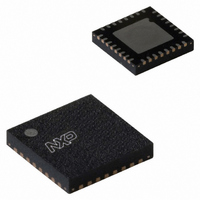
PN5110A0HN1/C2,118 NXP Semiconductors, PN5110A0HN1/C2,118 Datasheet - Page 19

PN5110A0HN1/C2,118
Manufacturer Part Number
PN5110A0HN1/C2,118
Description
IC TRANSMISSION MOD 32-HVQFN
Manufacturer
NXP Semiconductors
Datasheet
1.PN5110A0HN1C2118.pdf
(22 pages)
Specifications of PN5110A0HN1/C2,118
Rf Type
Read / Write
Frequency
13.56MHz
Features
ISO14443A / Mifare
Package / Case
32-VQFN Exposed Pad, 32-HVQFN, 32-SQFN, 32-DHVQFN
Lead Free Status / RoHS Status
Lead free / RoHS Compliant
Other names
935280541118
PN5110A0HN1/C2-T
PN5110A0HN1/C2-T
PN5110A0HN1/C2-T
PN5110A0HN1/C2-T
NXP Semiconductors
10. Limiting values
Table 13.
In accordance with the Absolute Maximum Rating System (IEC 60134).
11. Package information
Table 14.
12. Abbreviations
Table 15.
082733
Product short data sheet
Symbol
PV
P
T
ESDH
ESDM
ESDC
Package
HVQFN32
HVQFN40
Acronym
ASK
Initiator
Loadmodulation Index
Modulation Index
PCD
PICC
PCD → PICC
PICC → PCD
SAM
Target
J
tot
DD
Package Information
Limiting values
Abbreviations
Parameter
Supply voltage
Total power dissipation per package (V
and DV
Junction temperature range
ESD Susceptibility (Human Body model)
ESD Susceptibility (Machine model)
ESD Susceptibility (Charge Device model)
DD
in short cut mode)
The PN511 can be delivered in 2 different packages.
Remarks
8-bit parallel interface not supported
Supports the 8-bit parallel interface
Description
Amplitude Shift keying
Generates RF field at 13.56 MHz and starts the NFCIP-1 communication.
The load modulation index is defined as the card’s voltage ratio (Vmax - Vmin)/ (Vmax + Vmin)
measured at the card’s coil.
The modulation index is defined as the voltage ratio (Vmax - Vmin)/ (Vmax + Vmin).
Proximity Coupling Device. Definition for a Card reader/writer according to the ISO 14443
specification.
Proximity Cards. Definition for a contactless Smart Card according to the ISO 14443
specification.
Communication flow between a PCD and a PICC according to the ISO 14443A/Mifare.
Communication flow between a PICC and a PCD according to the ISO 14443A/Mifare.
Secure Access Module
Responds to initiator command either using load modulation scheme (RF field generated by
Initiator) or using modulation of self generated RF field (no RF field generated by initiator).
Rev. 3.3 — 13 June 2007
BUS
Conditions
1500 Ω, 100 pF;
JESD22-A114-B
0.75 μH, 200 pF;
JESD22-A114-A
Field induced model;
JESC22-C101-A
Min
-0.5
-
Transmission Module
© NXP B.V. 2007. All rights reserved.
Max
+4.0
200
100
2000
200
1000
PN511
Unit
V
mW
°C
V
V
V
19 of 22


