APT65GP60JDQ2 Microsemi Power Products Group, APT65GP60JDQ2 Datasheet - Page 8
APT65GP60JDQ2
Manufacturer Part Number
APT65GP60JDQ2
Description
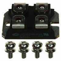
IGBT 600V 130A 431W SOT227
Manufacturer
Microsemi Power Products Group
Series
POWER MOS 7®r
Datasheet
1.APT65GP60JDQ2.pdf
(9 pages)
Specifications of APT65GP60JDQ2
Igbt Type
PT
Configuration
Single
Voltage - Collector Emitter Breakdown (max)
600V
Vce(on) (max) @ Vge, Ic
2.7V @ 15V, 65A
Current - Collector (ic) (max)
130A
Current - Collector Cutoff (max)
1.25mA
Input Capacitance (cies) @ Vce
7.4nF @ 25V
Power - Max
431W
Input
Standard
Ntc Thermistor
No
Mounting Type
Chassis Mount
Package / Case
ISOTOP
Lead Free Status / RoHS Status
Lead free / RoHS Compliant
Other names
APT65GP60JDQ2MI
APT65GP60JDQ2MI
APT65GP60JDQ2MI


Figure 28. Reverse Recovery Charge vs. Current Rate of Change
Figure 30. Dynamic Parameters vs. Junction Temperature
1400
1200
1000
140
120
100
800
600
400
200
200
150
100
Figure 32. Junction Capacitance vs. Reverse Voltage
1.2
1.0
0.8
0.6
0.4
0.2
0.0
80
60
40
20
50
0
Figure 26. Forward Current vs. Forward Voltage
0
0
0
0
0
1
-di
T
V
V
t
J
R
F
rr
F
T
= 125°C
200 400 600 800 1000 1200 1400 1600
= 400V
/dt, CURRENT RATE OF CHANGE (A/µs)
, ANODE-TO-CATHODE VOLTAGE (V)
J
, JUNCTION TEMPERATURE (°C)
0.5
25
60A
V
T
R
J
, REVERSE VOLTAGE (V)
= 125°C
15A
1.0
50
I
RRM
Q
T
10
J
rr
1.5
75
= 175°C
T
J
100
2.0
= 25°C
T
J
t
rr
= -55°C
Q
30A
125
2.5
rr
100 200
3.0
150
Figure 27. Reverse Recovery Time vs. Current Rate of Change
Figure 31. Maximum Average Forward Current vs. CaseTemperature
Figure 29. Reverse Recovery Current vs. Current Rate of Change
200
150
100
50
35
30
25
20
15
10
50
45
40
35
30
25
20
15
10
0
5
0
5
0
0
0
25
-di
-di
T
V
J
F
R
F
= 125°C
200 400 600 800 1000 1200 1400 1600
/dt, CURRENT RATE OF CHANGE(A/µs)
200 400 600 800 1000 1200 1400 1600
= 400V
/dt, CURRENT RATE OF CHANGE (A/µs)
50
Case Temperature (°C)
15A
75
60A
100
30A
30A
60A
125
Duty cycle = 0.5
T
15A
J
T
V
150
J
R
= 175°C
= 125°C
= 400V
175
Related parts for APT65GP60JDQ2
Image
Part Number
Description
Manufacturer
Datasheet
Request
R

Part Number:
Description:
IGBT 600V 100A 463W TO247
Manufacturer:
Microsemi Power Products Group
Datasheet:

Part Number:
Description:
IGBT 600V 198A 833W TO264
Manufacturer:
Microsemi Power Products Group
Datasheet:
Part Number:
Description:
IGBT 600V 41A 187W TO247
Manufacturer:
Microsemi Power Products Group
Datasheet:
Part Number:
Description:
MOSFET N-CH 600V 23A TO-247
Manufacturer:
Microsemi Power Products Group
Datasheet:

Part Number:
Description:
MOSFET N-CH 500V 17A TO-220
Manufacturer:
Microsemi Power Products Group
Datasheet:
Part Number:
Description:
MOSFET N-CH 1200V 3.5A TO-220
Manufacturer:
Microsemi Power Products Group
Datasheet:
Part Number:
Description:
MOSFET N-CH 500V 22A TO-247
Manufacturer:
Microsemi Power Products Group
Datasheet:
Part Number:
Description:
MOSFET N-CH 100V 75A TO-247
Manufacturer:
Microsemi Power Products Group
Datasheet:
Part Number:
Description:
MOSFET N-CH 200V 56A TO-247
Manufacturer:
Microsemi Power Products Group
Datasheet:
Part Number:
Description:
MOSFET N-CH 500V 27A TO-247
Manufacturer:
Microsemi Power Products Group
Datasheet:
Part Number:
Description:
MOSFET N-CH 300V 40A TO-247
Manufacturer:
Microsemi Power Products Group
Datasheet:
Part Number:
Description:
MOSFET N-CH 200V 59A TO-247
Manufacturer:
Microsemi Power Products Group
Datasheet:
Part Number:
Description:
MOSFET N-CH 500V 26A TO-247
Manufacturer:
Microsemi Power Products Group
Datasheet:
Part Number:
Description:
MOSFET N-CH 300V 40A TO-247
Manufacturer:
Microsemi Power Products Group
Datasheet:
Part Number:
Description:
MOSFET N-CH 200V 65A TO-247
Manufacturer:
Microsemi Power Products Group
Datasheet: