WLCL-TS Omron, WLCL-TS Datasheet - Page 22
WLCL-TS
Manufacturer Part Number
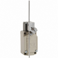
WLCL-TS
Description
SW LIMIT ADJ ROD LVR SPDT 10A
Manufacturer
Omron
Series
WLr
Type
General Purpose Limit Switchr
Datasheet
1.WL_COVER.pdf
(43 pages)
Specifications of WLCL-TS
Circuit
SPDT-DM/DB
Switch Function
On-Mom
Contact Rating @ Voltage
10A @ 125VAC
Actuator Type
Adjustable Rod
Mounting Type
Chassis Mount
Termination Style
Screw Terminal
Operating Force
142gf
Contact Form
1 NC / 4 NO
Contact Rating
10 Amps at 125 Volts
Actuator
Lever, Rod
Actuator Style
Flexible Rod
Operating Force Max
1.39N
Contact Voltage Ac Max
500V
Contact Voltage Dc Max
250V
Contact Current Ac Max
10A
Contact Current Dc Max
800mA
Switch Terminals
Screw
Current Rating (max)
10A
Operating Temp Range
-10C to 80C
Lead Free Status / RoHS Status
Lead free / RoHS Compliant
Lead Free Status / RoHS Status
Lead free / RoHS Compliant, Lead free / RoHS Compliant
Other names
WLCLTS
Z2752
Z2752


Ratings
General Ratings (Refer to these ratings before using the product.)
Screw Terminal Switches
Characteristics
Note: The figures in parentheses for dielectric strength, are those for overtravel
* The values are calculated at an operating temperature of +5°C to +35°C, and
Model
Basic models,
overtravel mod-
els, (except for
high-sensitivity
models), and
high-precision
models
High-sensitivity
overtravel mod-
els
Inrush
current
Degree of protection
Durability
Operating speed
Operating
frequency
Rated frequency
Insulation resistance
Contact resistance
Dielectric
strength
(50/60 Hz
for 1 min)
Vibration
resistance
Shock
resistance
Ambient operating
temperature
Ambient operating
humidity
Weight
an operating humidity of 40% to 70%RH. Contact your OMRON sales
representative for more detailed information on other operating environments.
(high-sensitivity) or connector models.
Long-life Switches
NC
NO
*
Item
Mechanical 30,000,000 operations min.
Electrical
Mechanical 120 operations/minute
Electrical
Between
terminals of
the same
polarity
Between
current-
carrying
metal part
and ground
Between each
terminal and
non-current-
carrying metal
part
Malfunction 10 to 55 Hz, 1.5-mm double amplitude
Destruction 1,000 m/s
Malfunction 300 m/s
voltage
115 AC
12 DC
24 DC
48 DC
115 DC
115 AC
115 DC
Rated
(V)
30 A max. (15 A max. *)
20 A max. (10 A max. *)
Non-inductive load (A)
Resistive
NC
IP67
30,000,000 operations min. (10 mA at
24 VDC, resistive load)
750,000 operations min. (10 A at 115
VAC, resistive load), but for high-pre-
cision models: 500,000 operations
min. (10 A at 115 VAC, resistive load)
1 mm/s to 1 m/s (in case of WLCA2)
30 operations/minute
50/60 Hz
100 MΩ min. (at 500 VDC)
25 mΩ max. (initial value for the built-
in switch when tested alone)
1,000 VAC (except connector models)
2,200 VAC (1,500 V)
2,200 VAC (1,500 V)
–10°C to +80°C (with no icing)
35% to 95%RH
Approx. 275 g (in case of WLCA2)
load
10
10
0.8
0.4
6
3
5
NO
2
NC
0.2
min.
2
3
6
4
2
Lamp
min.
load
—
—
NO
1.5
1.5
0.2
3
3
tive load
NC
Inductive load (A)
Induc-
10
10
—
—
0.8
6
3
NO
NC
5
Motor
load
0.2
—
—
6
4
2
NO
2.5
* For high-sensitivity overtravel models.
Direct-wired Connector and Pre-wired Connector Switches
Note: 1. The above figures are for steady-state currents.
Engineering Data
Electrical Durability: cosφ= 1
(Operating temperature: +5°C to +35°C, operating humidity: 40% to
70%RH)
Model
DC
AC
2. Inductive loads have a power factor of 0.4 min. (AC) and a time
3. A lamp load has an inrush current of 10 times the steady-state current.
4. A motor load has an inrush current of 6 times the steady-state current.
1,000
500
300
100
50
30
10
constant of 7 ms max. (DC).
12 DC
24 DC
48 DC
115 DC
115 AC
voltage
Rated
0
125 VAC
250 VAC
480 VAC
(V)
2
NC
0.8
Resistive
Non-inductive load (A)
3
3
3
3
load
4
NO
Operating frequency:
30 operations/min cos φ= 1
0.8
3
3
3
3
6
Lamp load
NC
0.2
3
3
3
3
8
NO
0.2
1.5
Switching current (A)
3
3
3
10
NC
0.8
Inductive
3
3
3
3
12
load
Inductive load (A)
WL/WLM
NO
0.8
3
3
3
3
Motor load
NC
0.2
3
3
3
3
NO
0.2
2.5
3
3
3
22
Related parts for WLCL-TS
Image
Part Number
Description
Manufacturer
Datasheet
Request
R

Part Number:
Description:
SWITCH LIMT DPST 6A ADJ ROD LEVR
Manufacturer:
Omron
Datasheet:
Part Number:
Description:
SWITCH LIMT DPST 6A ADJ ROD LEVR
Manufacturer:
Omron
Datasheet:
Part Number:
Description:
SWITCH LIMT DPST 6A ADJ ROD LEVR
Manufacturer:
Omron
Datasheet:
Part Number:
Description:
SWITCH LIMT DPST 6A ADJ ROD LEVR
Manufacturer:
Omron
Datasheet:
Part Number:
Description:
SWITCH LIMT DPST 6A ADJ ROD LEVR
Manufacturer:
Omron
Datasheet:
Part Number:
Description:
SWITCH LIMT DPST 6A ADJ ROD LEVR
Manufacturer:
Omron
Datasheet:
Part Number:
Description:
SWITCH LIMT DPST 6A ADJ ROD LEVR
Manufacturer:
Omron
Datasheet:
Part Number:
Description:
SWITCH LIMT DPST 6A ADJ ROD LEVR
Manufacturer:
Omron
Datasheet:
Part Number:
Description:
SWITCH LIMT DPST 6A ADJ ROD LEVR
Manufacturer:
Omron
Datasheet:
Part Number:
Description:
LIMIT SWITCH
Manufacturer:
Omron
Datasheet:
Part Number:
Description:
Basic / Snap Action / Limit Switches Limit Switch
Manufacturer:
Omron

Part Number:
Description:
SWITCH LIMIT ROLL W/OVRTRAVL 10A
Manufacturer:
Omron
Datasheet: