WLCL-TS Omron, WLCL-TS Datasheet - Page 24
WLCL-TS
Manufacturer Part Number
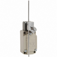
WLCL-TS
Description
SW LIMIT ADJ ROD LVR SPDT 10A
Manufacturer
Omron
Series
WLr
Type
General Purpose Limit Switchr
Datasheet
1.WL_COVER.pdf
(43 pages)
Specifications of WLCL-TS
Circuit
SPDT-DM/DB
Switch Function
On-Mom
Contact Rating @ Voltage
10A @ 125VAC
Actuator Type
Adjustable Rod
Mounting Type
Chassis Mount
Termination Style
Screw Terminal
Operating Force
142gf
Contact Form
1 NC / 4 NO
Contact Rating
10 Amps at 125 Volts
Actuator
Lever, Rod
Actuator Style
Flexible Rod
Operating Force Max
1.39N
Contact Voltage Ac Max
500V
Contact Voltage Dc Max
250V
Contact Current Ac Max
10A
Contact Current Dc Max
800mA
Switch Terminals
Screw
Current Rating (max)
10A
Operating Temp Range
-10C to 80C
Lead Free Status / RoHS Status
Lead free / RoHS Compliant
Lead Free Status / RoHS Status
Lead free / RoHS Compliant, Lead free / RoHS Compliant
Other names
WLCLTS
Z2752
Z2752


Note: 1. The indicator cover cannot be replaced on the molded terminals. In all cases the indicator does not light when the load is ON.
*1. Light-ON when operating means that the lamp lights when the Limit Switch contacts (NC) release, or when the actuator rotates or is pushed down.
*2. Light-ON when not operating means the lamp remains lit when the actuator is free, or when the Limit Switch contacts (NO) close when the actuator rotates or is
Indicator Windows
Indicator Covers
pushed down.
Operation
WL-LE
WL-LD
2. Leakage current from indicator circuit may cause load's malfunction. Please check the load's OFF current before use the indicator-equipped switch.
The indicator covered if outsert molded
from diecast aluminum and has
outstanding sealing properties.
Operation (i.e., light-ON when operating
or light-ON when not operating) depends
on whether a neon lamp or LED is used.
Indicators can be switched from light-ON
when operating and light-ON when not
operating, by simply rotating the indicator
holder by 180°.
(Molded terminals cannot be switched in
this way.)
Light-ON when Operating
Light-ON when Operating/Not Operating
Indicators
Light-ON when
operating *1
Light-ON when
not operating *2
LED at top
4
1
4
1
Built-in switch
Built-in switch
Internal circuits
Internal circuits
Za
Za
Power
Power
Light-ON when Not Operating
3
2
3
2
Load
Load
LED at bottom
Internal Circuits
WL-LE
WL-LD
Indicator
Contact Spring
Contact spring
Contact spring
The indicator is either a neon lamp or
an LED. Models with LED indicators
have a built-in rectifier stack, so it is not
necessary to change the polarity.
The built-in switch's terminal screws
are used to connect the indicator
terminal. Since the connection spring
(coil spring) is used for this connection,
it will not be necessary to connect the
indicator terminal. When a ground
terminal is provided however, a lead
wire must be used.
Neon lamp
Zener
diode
Rectifier stack
Resistor
Resistor
Resistor
WL/WLM
Rated
current
diode
LED
24
Related parts for WLCL-TS
Image
Part Number
Description
Manufacturer
Datasheet
Request
R

Part Number:
Description:
SWITCH LIMT DPST 6A ADJ ROD LEVR
Manufacturer:
Omron
Datasheet:
Part Number:
Description:
SWITCH LIMT DPST 6A ADJ ROD LEVR
Manufacturer:
Omron
Datasheet:
Part Number:
Description:
SWITCH LIMT DPST 6A ADJ ROD LEVR
Manufacturer:
Omron
Datasheet:
Part Number:
Description:
SWITCH LIMT DPST 6A ADJ ROD LEVR
Manufacturer:
Omron
Datasheet:
Part Number:
Description:
SWITCH LIMT DPST 6A ADJ ROD LEVR
Manufacturer:
Omron
Datasheet:
Part Number:
Description:
SWITCH LIMT DPST 6A ADJ ROD LEVR
Manufacturer:
Omron
Datasheet:
Part Number:
Description:
SWITCH LIMT DPST 6A ADJ ROD LEVR
Manufacturer:
Omron
Datasheet:
Part Number:
Description:
SWITCH LIMT DPST 6A ADJ ROD LEVR
Manufacturer:
Omron
Datasheet:
Part Number:
Description:
SWITCH LIMT DPST 6A ADJ ROD LEVR
Manufacturer:
Omron
Datasheet:
Part Number:
Description:
LIMIT SWITCH
Manufacturer:
Omron
Datasheet:
Part Number:
Description:
Basic / Snap Action / Limit Switches Limit Switch
Manufacturer:
Omron

Part Number:
Description:
SWITCH LIMIT ROLL W/OVRTRAVL 10A
Manufacturer:
Omron
Datasheet: