WLCL-TS Omron, WLCL-TS Datasheet - Page 31
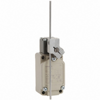
WLCL-TS
Manufacturer Part Number
WLCL-TS
Description
SW LIMIT ADJ ROD LVR SPDT 10A
Manufacturer
Omron
Series
WLr
Type
General Purpose Limit Switchr
Datasheet
1.WL_COVER.pdf
(43 pages)
Specifications of WLCL-TS
Circuit
SPDT-DM/DB
Switch Function
On-Mom
Contact Rating @ Voltage
10A @ 125VAC
Actuator Type
Adjustable Rod
Mounting Type
Chassis Mount
Termination Style
Screw Terminal
Operating Force
142gf
Contact Form
1 NC / 4 NO
Contact Rating
10 Amps at 125 Volts
Actuator
Lever, Rod
Actuator Style
Flexible Rod
Operating Force Max
1.39N
Contact Voltage Ac Max
500V
Contact Voltage Dc Max
250V
Contact Current Ac Max
10A
Contact Current Dc Max
800mA
Switch Terminals
Screw
Current Rating (max)
10A
Operating Temp Range
-10C to 80C
Lead Free Status / RoHS Status
Lead free / RoHS Compliant
Lead Free Status / RoHS Status
Lead free / RoHS Compliant, Lead free / RoHS Compliant
Other names
WLCLTS
Z2752
Z2752


Overtravel
General-purpose/High-sensitivity Models
Roller Lever R38
WLH2
WL01H2
WLG2
WL01G2
Adjustable Roller Lever
WLH12
WL01H12
WLG12
WL01G12
Rod Spring Lever
WLHAL5
WL01HAL5
Note: With WLHAL4, WL01HAL4, WLHAL5, and WL01HAL5, the actuator's tare is large, so depending on the installation direction, they may not be properly reset.
*1. The operating characteristics of WLH12, WL01HL12, WLG12, and WL01G12 are measured at the lever length of 38 mm.
*2. The operating characteristics of WLHL, WL01HL, WLGL, and WL01GL are measured at the rod length of 140 mm.
*3. The operating characteristics of WLHAL4, and WL01HAL4 are measured at the rod length of 380 mm.
Operating characteristics
Operating force
Release force
Pretravel
Overtravel
Movement Differential MD max.
Always install so that the actuator is facing downwards.
(125)
Adjustable range:
25 to 89
58.7
Note: 1. WL@G2 is identical to other models except in
428.5
* Stainless sintered roller
5
58.7
14.7
(4.9)
58.7
* Stainless sintered roller
Note: 1. WL@G12 is identical to other models except in
5
14.7
5
14.7
(4.9)
(4.9)
±0.2
* Piano wire
±0.2
±2
11
±0.2
2. The built-in switch for WLH2 is W-10FB3.
3. The built-in switch for WLG2 is W-10FB3-8.
65
38R
2. The built-in switch for WLH12 is W-10FB3.
3. The built-in switch for WLG12 is W-10FB3-8.
the shape of the set position marker plate.
OF max.
RF min.
PT
OT min.
(15.1)
30.2
40
(15.1)
the shape of the set position marker plate.
30.2
(15.1)
30.2
40
40
17.5 dia. (length: 7) *
Model
±0.7
±0.2
±0.7
±0.7
17.5 dia. (length: 7) *
±0.2
±0.2
2.3 dia. *
7.7
Four, M3.5
Four, M3.5
Three, M4
(length: 13)
JIS B0202 G½
Effective thread:
4 threads min.
Four, 5.2
dia. holes
M5 (length: 12)
Allen-head bolt
JIS B0202 G½
Effective thread:
4 threads min.
Four, 5.2
dia. holes
Three, M4
(length: 13)
M5 (length: 16)
Allen-head
bolt
Four, 5.2
dia. holes
Three, M4
(length: 13)
M5 (length: 16)
Allen-head
bolt
WLH2
WL01H2
JIS B0202 G½
Effective thread:
4 threads min.
15° ±5°
9.81 N
0.98 N
55°
12°
+0.2
0
+0.2
+0.2
0
0
........... For all models WL@ indicates a standard-load model and WL01@ indicates a microload model.
60 max.
53.2
65.2
67 max.
WLG2
WL01G2
53
60
41.5
42 max.
54
40
±1.5
42 max.
41.5
42 max.
41.5
±1.5
9.81 N
0.98 N
29.2
±0.8
±0.8
10°
35
±1.5
25.4
±1.5
±1.5
21.6
12.7
29.2
65°
13.1
2 9.2
35
25.4
±1.2
25.4
3 5
21.6
21.6
±1.5
12.7
±1.5
12.7
13 .1
7°
13.1
±1.2
±1.2
+2°
–1°
Four, M6
Depth: 15 min.
25.4
68.7
Four, M6
Depth: 15 min.
Four, M6
Depth: 15 min.
25.4
68.7
25.4
68.7
WLH12 *1
WL01H12 *1
15° ±5°
9.81 N
0.98 N
55°
12°
Adjustable Rod Lever
WLHL
WL01HL
WLGL
WL01GL
Adjustable Rod Lever
WLHAL4
WL01HAL4
Note: Unless otherwise indicated, a tolerance of ±0.4 mm applies to all
OF and RF for WLH12 and WL01H12, with a lever length of
89 mm.
WLG12 *1
WL01G12 *1
9.81 N
0.98 N
10°
OF
RF
dimensions.
65°
7°
+2°
–1°
Adjustable range:
25 to 140
Adjustable range:
350 to 380
WLHL *1
WL01HL *1
58.7
WLH12, WLA01H12
5
14.7
15° ±5°
(4.9)
2.84 N
0.25 N
58.7
5
±0.2
14 .7
* Stainless sintered roller
Note: 1. WL@GL is identical to other models except in
55°
12°
(4.9)
* Stainless steel rod
±0.2
4.18 N
0.42 N
(15.1)
30.2
40
2. The built-in switch for WLHL is W-10FB3.
3. The built-in switch for WLGL is W-10FB3-8.
9
(15.1)
30.2
the shape of the set position marker plate.
±0.7
40
Four, M3.5
±0.2
3 ±0.2 dia.
(length: 160) *
WLGL *2
WL01GL *2
3.2 dia. *
±0.7
±0.2
12 .8
8
2.84 N
0.25 N
10°
Three, M4
(length: 13)
Four, 5.2
dia. holes
M8 (length: 12)
Allen-head
lock screw
M5 (length: 12)
Allenhead bolt
65°
6 5
JIS B0202 G½
Effective thread:
4 threads min.
7°
Three, M4
(length: 13)
Four, 5.2
dia. holes
+2°
–1°
M5 (length: 12)
Allen-head
bolt
JIS B0202 G½
Effective thread:
4 threads min.
+0.2
0
+0.2
0
WLHAL4 *3
WL01HAL4 *3
15° ±5°
WLG12, WL01G12
0.98 N
0.15 N
55°
12°
55 max.
46
41.5
42 max.
WL/WLM
54.5
±1.5
29.2
41.5
42 max.
4.18 N
0.42 N
35
25.4
±1.5
21.6
12.7
13.1
±1.2
±1.5
2 9.2
2 5 .4
3 5
21.6
±1.5
12 .7
13 .1
±1.2
WLHAL5
WL01HAL5
Four, M6
Depth: 15 min.
15° ±5°
25.4
68.7
0.90 N
0.09 N
Four, M6
Depth: 15 mi
2 5 .4
6 8 .7
55°
12°
31
Related parts for WLCL-TS
Image
Part Number
Description
Manufacturer
Datasheet
Request
R

Part Number:
Description:
SWITCH LIMT DPST 6A ADJ ROD LEVR
Manufacturer:
Omron
Datasheet:
Part Number:
Description:
SWITCH LIMT DPST 6A ADJ ROD LEVR
Manufacturer:
Omron
Datasheet:
Part Number:
Description:
SWITCH LIMT DPST 6A ADJ ROD LEVR
Manufacturer:
Omron
Datasheet:
Part Number:
Description:
SWITCH LIMT DPST 6A ADJ ROD LEVR
Manufacturer:
Omron
Datasheet:
Part Number:
Description:
SWITCH LIMT DPST 6A ADJ ROD LEVR
Manufacturer:
Omron
Datasheet:
Part Number:
Description:
SWITCH LIMT DPST 6A ADJ ROD LEVR
Manufacturer:
Omron
Datasheet:
Part Number:
Description:
SWITCH LIMT DPST 6A ADJ ROD LEVR
Manufacturer:
Omron
Datasheet:
Part Number:
Description:
SWITCH LIMT DPST 6A ADJ ROD LEVR
Manufacturer:
Omron
Datasheet:
Part Number:
Description:
SWITCH LIMT DPST 6A ADJ ROD LEVR
Manufacturer:
Omron
Datasheet:
Part Number:
Description:
LIMIT SWITCH
Manufacturer:
Omron
Datasheet:
Part Number:
Description:
Basic / Snap Action / Limit Switches Limit Switch
Manufacturer:
Omron

Part Number:
Description:
SWITCH LIMIT ROLL W/OVRTRAVL 10A
Manufacturer:
Omron
Datasheet: