WLD3-TS Omron, WLD3-TS Datasheet - Page 40
WLD3-TS
Manufacturer Part Number
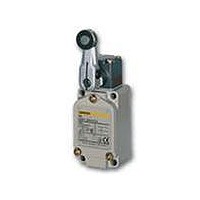
WLD3-TS
Description
SWTCH LMT DPST 6A TOP BALL PLNGR
Manufacturer
Omron
Series
WLr
Datasheet
1.WL_COVER.pdf
(43 pages)
Specifications of WLD3-TS
Circuit
SPDT-DM/DB
Switch Function
On-Mom
Contact Rating @ Voltage
10A @ 125VAC
Actuator Type
Round (Pin Plunger)
Mounting Type
Chassis Mount
Termination Style
Screw Terminal
Operating Force
2720gf
Lead Free Status / RoHS Status
Lead free / RoHS Compliant
Other names
WLD3TS


Built-in Switch
Do not remove or replace the built-in switch. If the position of the built-
in switch moves, it can cause reduced performance, and if the
insulation sheet moves (separator), the insulation may become
ineffective.
Tightening Torque
Installing the Switch
To install the Switch, make a mounting panel, as shown in the
following diagram, and tighten screws using the correct torque.
Mounting
Mounting
1.
6.
5.
• If screws are too loose they can lead to an early malfunction of the
• In particular, when changing the direction of the Head, make sure
Front Mountig/
Rear Mountig
Side Mountig
Switch, so ensure that all screws are tightened using the correct
torque.
that all screws are tightened again to the correct torque. Do not
allow foreign objects to fall into the Switch.
In case of side mounting for
overtravel,90
Front Mountig :
Rear Mountig :
58.7
Two, 5.2
3.
4.
2.
WL
±0.15
°
No.
WL@-@@2N
1.
2.
3.
4.
5.
30.2
23
+0.2
0
Four, 5.2
or M5 tapped holes
Four, 6.2
±0.15
dia. holes
±0.15
Head mounting
screw
Cover mounting
screw
Allen-head bolt
(for securing the
lever)
Terminal screw
Connector
64
±0.15
+0.2
+0.2
0
0
Type
dia. holes
dia. holes
0.78 to 0.88 N·m
1.18 to 1.37 N·m
4.90 to 5.88 N·m
0.59 to 0.78 N·m
1.77 to 2.16 N·m
Appropriate
Mounting
locations
Mounting
locations
tightening
torque
Connectors
Either the easy-to-use Allen-head nut or the SC Connector can be
used as connectors. To ensure high-sealing properties, use the SC
Connector. Refer to Limit Switch Connectors for details on SC
Connectors.
Wiring
Rotating Lever Set Position (General-purpose or Spatter-
prevention Switches Only)
All rotating lever models, except the fork lever lock models, have a set
position marker plate. (See page 23.) After operation, set the indicator
needle on the marker plate so that is in the convex section of the
bearing.
Operation Set Position (Long-life Switches Only)
For all Long-life Switching, there is a set position marker slit on the
rubber cap of the head. After operation, set the slit on the rubber cap
so that the fluorescent color on the shaft section can be seen.
Terminal Plate
By using a short circuit plate, as shown in the following diagram, the
Switch can be fabricated into a single-polarity double-break switch.
When ordering, specify WL Terminal Plate (product code: WL-
9662F).
Indicator
Indicator-equipped switch has contacts and indicator in parallel.
When contacts are open, leakage current flows through the indicator
circuit and may cause load's malfunction.
Please check the load's OFF current before use the indicator-
equipped switch.
• Use 1.25-mm
• The ground terminal is only installed on models with ground
terminals for wiring.
terminals.
Crimp Terminal External
Dimensions
D dia.
dz dia. : 4.3
D dia. : 4.5
B
L
F
l
: 8.5
: 21.0
: 7.8
: 9.0 (mm)
l
2.5
9
2
±0.2
+0.2
lead wires and M4-insulation covered crimp
0
L
2.1R
F
dz dia.
4.2
COM
9
+0.1
0
7
B
16
3.5
±0.15
t = 0.6 Brass plate
Wiring Method
Switch Box Section
23
Ground terminal
±0.4
NO terminal
NC terminal
2R
7.1
WL/WLM
3R
40
Related parts for WLD3-TS
Image
Part Number
Description
Manufacturer
Datasheet
Request
R

Part Number:
Description:
SWTCH LMT DPST 6A TOP BALL PLNGR
Manufacturer:
Omron
Datasheet:
Part Number:
Description:
SWTCH LMT DPST 6A TOP BALL PLNGR
Manufacturer:
Omron
Datasheet:
Part Number:
Description:
LS BALL PLUNGER
Manufacturer:
Omron
Datasheet:
Part Number:
Description:
Basic / Snap Action / Limit Switches Limit Switch
Manufacturer:
Omron

Part Number:
Description:
SWITCH LIMIT ROLL W/OVRTRAVL 10A
Manufacturer:
Omron
Datasheet:

Part Number:
Description:
SWITCH LIMIT ADJ ROLL LEVER 10A
Manufacturer:
Omron
Datasheet:
Part Number:
Description:
SWITCH LIMIT ADJ ROLL W/OVTRAVEL
Manufacturer:
Omron
Datasheet:
Part Number:
Description:
SWITCH LIMIT ROLL LEVER SPDT 10A
Manufacturer:
Omron
Datasheet:

Part Number:
Description:
SW LIMIT ADJ ROD LVR SPDT 10A
Manufacturer:
Omron
Datasheet:
Part Number:
Description:
SWITCH LIMIT DPST 6A W/O LEVER
Manufacturer:
Omron
Datasheet:
Part Number:
Description:
SWITCH LIMIT DPST 6A FLEXIBL ROD
Manufacturer:
Omron
Datasheet:
Part Number:
Description:
SWITCH LIMT DPST 6A ADJ ROL LEVR
Manufacturer:
Omron
Datasheet:
Part Number:
Description:
SWITCH LIMIT DPST 6A ROLLR LEVER
Manufacturer:
Omron
Datasheet:
Part Number:
Description:
SWITCH LIMIT DPST 6A ROLLR LEVER
Manufacturer:
Omron
Datasheet: