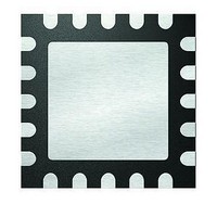
MCP4461T-103E/ML Microchip Technology, MCP4461T-103E/ML Datasheet - Page 93

MCP4461T-103E/ML
Manufacturer Part Number
MCP4461T-103E/ML
Description
IC DGTL POT 257TAPS 10K 20QFN
Manufacturer
Microchip Technology
Datasheet
1.MCP4441-103EML.pdf
(100 pages)
Specifications of MCP4461T-103E/ML
Package / Case
20-VFQFN Exposed Pad
Temperature Coefficient
150 ppm/°C Typical
Taps
257
Resistance (ohms)
10K
Number Of Circuits
4
Memory Type
Non-Volatile
Interface
I²C, 2-Wire Serial
Voltage - Supply
2.7 V ~ 5.5 V
Operating Temperature
-40°C ~ 125°C
Mounting Type
Surface Mount
Number Of Pots
Quad
Taps Per Pot
257
Resistance
10 KOhms
Wiper Memory
Non Volatile
Buffered Wiper
Buffered
Digital Interface
I2C
Operating Supply Voltage
2.7 V to 5.5 V
Supply Current
600 uA
Maximum Operating Temperature
+ 125 C
Minimum Operating Temperature
- 40 C
Description/function
Quad I2C Digital POT with Nonvolatile Memory
Mounting Style
SMD/SMT
Supply Voltage (max)
5.5 V
Supply Voltage (min)
2.7 V
Lead Free Status / RoHS Status
Lead free / RoHS Compliant
Available stocks
Company
Part Number
Manufacturer
Quantity
Price
Part Number:
MCP4461T-103E/ML
Manufacturer:
MICROCHIP/微芯
Quantity:
20 000
FIGURE B-6:
Diagram.
The characteristics of the wiper are determined by the
characteristics of the wiper switch at each of the
resistor networks tap points.
example of a wiper switch. As the device operational
voltage becomes lower, the characteristics of the wiper
switch change due to a lower voltage on the V
Figure B-7
When the transistor is turned off, the switch resistance
is in the Giga Ωs. When the transistor is turned on, the
switch resistance is dependent on the V
V
FIGURE B-7:
© 2010 Microchip Technology Inc.
R
Note 1:
WCn
AB
Note 1: Wiper Resistance (R
V
N
N
N
N
WCn
WC
R
R
R
R
voltages. This resistance is referred to as R
N
N
N
n-1
n-2
n-3
S
S
S
S
1
n
0
A
B
shows an implementation of a wiper switch.
V
The wiper resistance is dependent on
several factors including, wiper code,
device V
and W), and temperature.
V
V
voltages at the wiper switch nodes
(V
WC(n-2)
A
B
“gate”
“gate”
R
R
R
R
G
W
W
W
, V
W
(1)
(1)
(1)
(1)
W
DD
and V
NMOS
PMOS
Resistor Network Block
Wiper Switch.
, Terminal voltages (on A, B
R
NMOS
PMOS
W
R
WCn
W
(1)
(1)
).
Figure B-7
W
V
) depends on the
G
(V
Wiper
V
DD
W
G
/V
shows an
, V
DV
V
G
SS
W
signal.
W
G
)
W
W
and
.
So looking at the wiper voltage (V
3.0V and 1.8V data gives the graphs in
Figure
0.8V, the voltage increases nonlinearly. Since V = I * R,
and the current (I
device resistance increased nonlinearly at around
wiper code 160.
FIGURE B-8:
Wiper Code (V
FIGURE B-9:
Wiper Code (V
1.4
1.2
1.0
0.8
0.6
0.4
0.2
0.0
1.2
1.0
0.8
0.6
0.4
0.2
0.0
B-9. In the 1.8V graph, as the V
0
0
32
32
MCP444X/446X
DD
DD
64
W
64
= 3.0V, I
= 1.8V, I
) is constant, it means that the
Wiper Voltage (V
Wiper Voltage (V
96
96
Wiper Code
Wiper Code
128
128
W
W
= 190
= 190
160
160
DS22265A-page 93
192
192
µ
µ
Figure B-8
W
A).
A).
W
W
W
approaches
) vs.
224
) vs.
224
) for the
-40C
+25C
+85C
+125C
-40C
+25C
+85C
+125C
256
256
and


