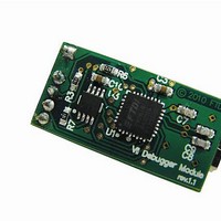
VNC2 DEBUG MODULE FTDI, VNC2 DEBUG MODULE Datasheet - Page 9

VNC2 DEBUG MODULE
Manufacturer Part Number
VNC2 DEBUG MODULE
Description
Interface Modules & Development Tools USB Vinculum-II Debug/Programmer Mod
Manufacturer
FTDI
Datasheet
1.VNC2_DEBUG_MODULE.pdf
(16 pages)
Specifications of VNC2 DEBUG MODULE
Interface Type
USB, Serial, UART, FIFO, SPI
Data Bus Width
Serial, 8 bit
Operating Supply Voltage
5 V
Product
Interface Development Tools
Ic Product Type
Debugger / Programmer
Kit Contents
Miniature Board, USB Connector
Features
Low USB Bandwidth Consumption, Programming And Debugging For VNC2 IC Designs
Svhc
No SVHC (18-Jun-2010)
Rohs Compliant
Yes
Supported Devices
VNC2
For Use With/related Products
VNC2
Lead Free Status / RoHS Status
Lead free / RoHS Compliant
Document Reference No.: FT_000254
VNC2 Debug Module Datasheet Version 1.0
Clearance No.: FTDI# 149
`
3.6 Confirm Debug Connection Using IDE
Having connected the VNC2 debug module to the VNC2 hardware, a user can verify the operation of the
debug interface operation using the Vinculum II IDE development software.
Simply connect the debug module to a PC via the mini-B USB connector. Open the Vinculum II IDE
software.
Under the ‘Debug’ tab the ‘VII Debugger Module’ should be listed as an available debug
interface. Once detected, users can now use the VNC2 debug module to debug code and program the
VNC2 device.
Figure 3.4 VNC2 Connection Confirmation on Vinculum-II IDE
Copyright © 2010 Future Technology Devices International Limited
8


