NCP3125AGEVB ON Semiconductor, NCP3125AGEVB Datasheet - Page 16
NCP3125AGEVB
Manufacturer Part Number
NCP3125AGEVB
Description
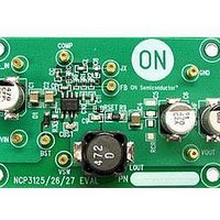
Power Management Modules & Development Tools NCP3125 Evaluation Board
Manufacturer
ON Semiconductor
Type
DC/DC Switching Converters, Regulators & Controllersr
Datasheets
1.NCP3125AGEVB.pdf
(22 pages)
2.NCP3125AGEVB.pdf
(1 pages)
3.NCP3125AGEVB.pdf
(4 pages)
4.NCP3125AGEVB.pdf
(1 pages)
Specifications of NCP3125AGEVB
Maximum Operating Temperature
+ 125 C
Minimum Operating Temperature
- 40 C
Operating Supply Voltage
4.5 V to 13.2 V
Product
Power Management Modules
For Use With/related Products
NCP3125
Lead Free Status / RoHS Status
Lead free / RoHS Compliant


C
f
R
R
R
The cross over of the overall feedback occurs at F
C
F
F
R
R
R
V
V
used to calculate the transconductance output compensation
network as follows:
C
F
gm
R
R
1.152 kHz +
cross
C
0.96 nF +
F
LC
PO
PO
F
1
2
F
F
1
2
F
IN
ramp
C
1
2
The cross over combined compensation network can be
PO
F
+
84 nF +
+
C
2p
( 2p )
C
+
2p
2
F
1.152 kHz
R
= Feed through capacitor
= Crossover frequency
= Top resistor divider
= Bottom resistor divider
= Feed through resistor
( 2p )
= Feed through capacitor
= Frequency of the output inductor and capacitor
= Pole frequency
= Top of resistor divider
= Bottom of resistor divider
= Feed through resistor
= Input voltage
= Peak−to−peak voltage of the ramp
= Compensation capacitor
= Pole frequency
= Transconductance of amplifier
= Top of resistor divider
= Bottom of resistor divider
1
PO
1
) R
C
1
2
31.6 kW
F
R
2
F
( 0.96 )
2
) R
R
R
1
2
R
) R
R
10 kW ) 31.6 kW
2
2
1
1
20 kW ) 10 kW
) R
31.6 kW ) 20 kW
F
R
R
gm ³
10 kW
F
1
2
) R
) R
R
2
2
) R
F
31.6 kW ) 10 kW
R
1
1
4 ms
R
20 kW ) 10 kW
31.6 kW ) 20 kW
PO
F
f
cross
10 kW ) 31.6 kW
http://onsemi.com
:
R
(eq. 42)
F
) R
16
1
31.6 kW
FLC
V
20 kW
ramp
V
IN
30 kHz
³
20 kW ) 31.6 kW
(eq. 41)
(eq. 40)
3.102 kHz
1.1 V
12 V
Related parts for NCP3125AGEVB
Image
Part Number
Description
Manufacturer
Datasheet
Request
R

Part Number:
Description:
4 A Synchronous PWM Switching Converter
Manufacturer:
ON Semiconductor
Datasheet:
Part Number:
Description:
BOARD EVALUATION NCP3125 CERAMIC
Manufacturer:
ON Semiconductor
Datasheet:
Part Number:
Description:
ON Semiconductor [VOLTAGE REGULATOR]
Manufacturer:
ON Semiconductor
Datasheet:
Part Number:
Description:
357-036-542-201 CARDEDGE 36POS DL .156 BLK LOPRO
Manufacturer:
ON Semiconductor
Datasheet:
Part Number:
Description:
357-036-542-201 CARDEDGE 36POS DL .156 BLK LOPRO
Manufacturer:
ON Semiconductor
Datasheet:
Part Number:
Description:
357-036-542-201 CARDEDGE 36POS DL .156 BLK LOPRO
Manufacturer:
ON Semiconductor
Datasheet:
Part Number:
Description:
357-036-542-201 CARDEDGE 36POS DL .156 BLK LOPRO
Manufacturer:
ON Semiconductor
Datasheet:
Part Number:
Description:
357-036-542-201 CARDEDGE 36POS DL .156 BLK LOPRO
Manufacturer:
ON Semiconductor
Datasheet:
Part Number:
Description:
357-036-542-201 CARDEDGE 36POS DL .156 BLK LOPRO
Manufacturer:
ON Semiconductor
Datasheet:
Part Number:
Description:
357-036-542-201 CARDEDGE 36POS DL .156 BLK LOPRO
Manufacturer:
ON Semiconductor
Datasheet:
Part Number:
Description:
357-036-542-201 CARDEDGE 36POS DL .156 BLK LOPRO
Manufacturer:
ON Semiconductor
Datasheet:
Part Number:
Description:
357-036-542-201 CARDEDGE 36POS DL .156 BLK LOPRO
Manufacturer:
ON Semiconductor
Datasheet:
Part Number:
Description:
357-036-542-201 CARDEDGE 36POS DL .156 BLK LOPRO
Manufacturer:
ON Semiconductor
Datasheet:
Part Number:
Description:
Manufacturer:
ON Semiconductor
Datasheet: