NCP3125AGEVB ON Semiconductor, NCP3125AGEVB Datasheet - Page 8
NCP3125AGEVB
Manufacturer Part Number
NCP3125AGEVB
Description
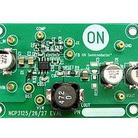
Power Management Modules & Development Tools NCP3125 Evaluation Board
Manufacturer
ON Semiconductor
Type
DC/DC Switching Converters, Regulators & Controllersr
Datasheets
1.NCP3125AGEVB.pdf
(22 pages)
2.NCP3125AGEVB.pdf
(1 pages)
3.NCP3125AGEVB.pdf
(4 pages)
4.NCP3125AGEVB.pdf
(1 pages)
Specifications of NCP3125AGEVB
Maximum Operating Temperature
+ 125 C
Minimum Operating Temperature
- 40 C
Operating Supply Voltage
4.5 V to 13.2 V
Product
Power Management Modules
For Use With/related Products
NCP3125
Lead Free Status / RoHS Status
Lead free / RoHS Compliant


External Soft−Start
which reduces inrush current and overshoot of the output
voltage. Soft−start is achieved by using the internal current
source of 10.5 mA (typ), which charges the external
integrator capacitor of the OTA. Figure 18 is a typical
soft−start sequence. The sequence begins once V
V
programming is complete. The current sourced out of the
COMP pin continually increases the voltage until regulation
is reached. Once the voltage reaches 400 mV logic is
enabled. When the voltage exceeds 900 mV, switching
begins. Current is sourced out of the COMP pin, placing the
regulator into open loop operation until 800 mV is sensed at
the FB pin. Once 800 mV is sensed at the FB pin, open loop
operation ends and closed loop operation begins. In closed
loop operation, the OTA is capable of sourcing and sinking
120 mA.
BG Comparator
BG Comparator Output
COMP
BST
The NCP3125 features an external soft−start function,
DAC Voltage
COMP
VCC
VFB
Vout
BG
TG
Figure 17. Enable/Disable Driver State Diagram
TG
BG
0.9 V
UVLO
surpass their UVLO thresholds and OCP
4.2 V
Delay
POR
Figure 18. Soft−Start Sequence
Trip Set
Current
50 mV
COMP
Delay
500 mV
0.9 V
Soft−Start Normal Operation
3.85 V
UVLO
http://onsemi.com
IN
and
8
Overcurrent Threshold Setting
550 mV, by adding a resistor (R
GND. During a short period of time following V
over UVLO threshold, an internal 10 mA current (I
sourced from the ISET pin, creating a voltage drop across
R
internal voltage ramp. Once the internal stepped voltage
reaches the R
power is cycled. The overall time length for the OC setting
procedure is approximately 9 ms. Connecting an R
resistor between ISET and GND, the programmed threshold
will be:
I
I
R
R
connected, the device switches the OCP threshold to a fixed
375 mV value. An internal safety clamp on ISET is triggered
as soon as ISET voltage reaches 700 mV, enabling the
375 mV fixed threshold and ending the OCP setting period.
The current trip threshold tolerance is ±25 mV. The
accuracy is best at the highest set point (550 mV). The
accuracy will decrease as the set point decreases. MOSFET
tolerances with temperature and input voltage will vary the
over current set threshold operating point. A graph of the
typical current limit set thresholds at 4.5 V and 12 V is
shown in Figure .
OCSET
OCth
SET
DS(on)
SET
NCP3125 overcurrent threshold can be set from 50 mV to
I
The R
6.5
5.5
4.5
3.5
2.5
OCth
7
6
5
4
3
2
. The voltage drop is compared against a stepped
5 6
= Current trip threshold
= Current set resistor
+
= Sourced current
= On resistance of the low side MOSFET
SET
Figure 19. R
I
OCSET
7 8
values range from 5 kW to 55 kW. If R
SET
R
DS(on)
voltage, the value is stored internally until
* R
9 10 11 12 13 14 15 16 17 18 19 20 21
SET
SET
³ 4.2 A +
R
Value for Output Current
SET
12 V
5 V
(kW)
SET
10 mA * 21 kW
) between ISET and
50 mW
OCSET
SET
IN
(eq. 1)
rising
is not
SET
) is
Related parts for NCP3125AGEVB
Image
Part Number
Description
Manufacturer
Datasheet
Request
R

Part Number:
Description:
4 A Synchronous PWM Switching Converter
Manufacturer:
ON Semiconductor
Datasheet:
Part Number:
Description:
BOARD EVALUATION NCP3125 CERAMIC
Manufacturer:
ON Semiconductor
Datasheet:
Part Number:
Description:
ON Semiconductor [VOLTAGE REGULATOR]
Manufacturer:
ON Semiconductor
Datasheet:
Part Number:
Description:
357-036-542-201 CARDEDGE 36POS DL .156 BLK LOPRO
Manufacturer:
ON Semiconductor
Datasheet:
Part Number:
Description:
357-036-542-201 CARDEDGE 36POS DL .156 BLK LOPRO
Manufacturer:
ON Semiconductor
Datasheet:
Part Number:
Description:
357-036-542-201 CARDEDGE 36POS DL .156 BLK LOPRO
Manufacturer:
ON Semiconductor
Datasheet:
Part Number:
Description:
357-036-542-201 CARDEDGE 36POS DL .156 BLK LOPRO
Manufacturer:
ON Semiconductor
Datasheet:
Part Number:
Description:
357-036-542-201 CARDEDGE 36POS DL .156 BLK LOPRO
Manufacturer:
ON Semiconductor
Datasheet:
Part Number:
Description:
357-036-542-201 CARDEDGE 36POS DL .156 BLK LOPRO
Manufacturer:
ON Semiconductor
Datasheet:
Part Number:
Description:
357-036-542-201 CARDEDGE 36POS DL .156 BLK LOPRO
Manufacturer:
ON Semiconductor
Datasheet:
Part Number:
Description:
357-036-542-201 CARDEDGE 36POS DL .156 BLK LOPRO
Manufacturer:
ON Semiconductor
Datasheet:
Part Number:
Description:
357-036-542-201 CARDEDGE 36POS DL .156 BLK LOPRO
Manufacturer:
ON Semiconductor
Datasheet:
Part Number:
Description:
357-036-542-201 CARDEDGE 36POS DL .156 BLK LOPRO
Manufacturer:
ON Semiconductor
Datasheet:
Part Number:
Description:
Manufacturer:
ON Semiconductor
Datasheet: