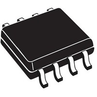
PCF8563T/5,518 NXP Semiconductors, PCF8563T/5,518 Datasheet - Page 25

PCF8563T/5,518
Manufacturer Part Number
PCF8563T/5,518
Description
IC RTC/CALENDAR 8SOIC
Manufacturer
NXP Semiconductors
Type
Clock/Calendarr
Datasheet
1.PCF8563TF4118.pdf
(45 pages)
Specifications of PCF8563T/5,518
Package / Case
*
Time Format
HH:MM:SS (24 hr)
Date Format
YY-MM-DD-dd
Memory Size
128b (16 x 8)
Interface
I²C, 2-Wire Serial
Voltage - Supply
1.8 V ~ 5.5 V
Operating Temperature
-40°C ~ 85°C
Mounting Type
*
Function
Clock, Calendar, Alarm, Timer
Supply Voltage (max)
5.5 V
Supply Voltage (min)
1 V
Maximum Operating Temperature
+ 85 C
Minimum Operating Temperature
- 40 C
Mounting Style
SMD/SMT
Rtc Bus Interface
I2C
Supply Current
+/- 50 mA
Bus Type
Serial (2-Wire, I2C)
Operating Supply Voltage (typ)
2.5/3.3/5V
Package Type
SO
Operating Supply Voltage (max)
5.5V
Operating Supply Voltage (min)
1.8V
Operating Temperature Classification
Industrial
Operating Temperature (max)
85C
Operating Temperature (min)
-40C
Pin Count
8
Mounting
Surface Mount
Lead Free Status / RoHS Status
Lead free / RoHS Compliant
Lead Free Status / RoHS Status
Lead free / RoHS Compliant, Lead free / RoHS Compliant
Other names
568-6650-2
PCF8563T/5,518
PCF8563T/5,518
NXP Semiconductors
PCF8563
Product data sheet
9.6 Interface watchdog timer
During read/write operations, the time counting circuits are frozen. To prevent a situation
where the accessing device becomes locked and does not clear the interface, the
PCF8563 has a built in watchdog timer. Should the interface be active for more than 1 s
from the time a valid slave address is transmitted, then the PCF8563 will automatically
clear the interface and allow the time counting circuits to continue counting. The watchdog
will trigger between 1 s and 2 s after receiving a valid slave address. Each time the
watchdog period is exceeded, 1 s will be lost from the time counters.
The watchdog is implemented to prevent the excessive loss of time due to interface
access failure e.g. if main power is removed from a battery backed-up system during an
interface access.
Fig 22. Interface watchdog timer
a. Correct data transfer: read or write
b. Incorrect data transfer; read or write
WD timer
WD timer
counters
counters
data
data
time
time
All information provided in this document is subject to legal disclaimers.
START
START
Rev. 8 — 18 November 2010
SLAVE ADDRESS
SLAVE ADDRESS
running
running
DATA
DATA
time counters frozen
WD timer tracking
time counters frozen
WD timer tracking
DATA
DATA
t < 1 s
1 s < t < 2 s
data transfer fail
STOP
Real-time clock/calendar
running
PCF8563
© NXP B.V. 2010. All rights reserved.
WD trips
running
013aaa420
013aaa421
25 of 45


