MNZB-DKC-900 MeshNetics, MNZB-DKC-900 Datasheet - Page 17
MNZB-DKC-900
Manufacturer Part Number
MNZB-DKC-900
Description
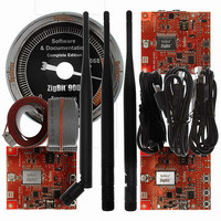
KIT DEV ZIGBIT 900 COMPLETE 1YR
Manufacturer
MeshNetics
Type
802.15.4/Zigbeer
Datasheet
1.MNZB-EVB-900-B0.pdf
(56 pages)
Specifications of MNZB-DKC-900
Frequency
868MHz, 915MHz
For Use With/related Products
MNZB-900-B0
Lead Free Status / RoHS Status
Lead free / RoHS Compliant
Other names
758-1009


© 2008 MeshNetics
Table 3. Expansion slot pinout
Pin
1
2
3
4
5
6
7
8
9
10
11
12
13
14
15
16
Name
UART_RTS
UART_TXD
UART_CTS
UART_RXD
GND
GND
I2C_CLK
I2C_DATA
+3.6V
V_XX
RESET
USART_TXD
USART_RXD
USART_CLK
GND
ADC_INPUT1
Z I G B I T ™ 9 0 0 D E V E L O P M E N T K I T 1 . 3
I/O
Input
Input
Output
Output
Input
Bidirectional
Output
Output
Input
Output
Input
Input
Input
Description
Request to Send Pin. RS-232 level.
Transmit Data Pin (meaning that the host
device will transmit data to this line). RS-232
level.
Clear To Send signal from the module.
Active low. RS-232 level.
Receive Data Pin (meaning that the host
device will receive data from this line). RS-232
level.
Digital/analog ground
Digital/analog ground
I
of the module via low-voltage level translators.
For details, refer to ZigBit 900 datasheet [1].
I
of the module via low-voltage level translators.
For details, refer to ZigBit 900 datasheet [1].
Output of internal voltage regulator. Normally,
the voltage is 3.6 V.
ZigBit 900 supply voltage
Reset Pin. Active low. This pin is connected in
parallel to the RESET button on the board.
This is Transmit Data Pin for USART0
interface of the ZigBit 900 module. It is
connected directly to the USART0_TXD pin of
the module. Digital logic level. For details, refer
to ZigBit 900 datasheet [1].
This is Receive Data Pin for USART0
interface of the ZigBit 900 module. It is
connected directly to the USART0_RXD pin of
the module. Digital logic level. For details, refer
to ZigBit 900 datasheet [1].
This is Clock Data Pin for USART0 interface
of the ZigBit 900 module. It is connected
directly to the USART0_EXTCLK pin of the
module. Digital logic level. For details, refer to
ZigBit 900 datasheet [1].
Digital/analog ground
ADC input. This pin is connected directly to the
ADC_INPUT_1 pin of the module. For details,
refer to ZigBit 900 datasheet [1].
2
2
C clock. It is connected to the I2C_CLK pin
C data. It is connected to the I2C_DATA pin
U S E R ’ S G U I D E
Page 17/56
Related parts for MNZB-DKC-900
Image
Part Number
Description
Manufacturer
Datasheet
Request
R

Part Number:
Description:
KIT DEV ZIGBIT 2.4GHZ COMPLETE
Manufacturer:
MeshNetics
Datasheet:


Part Number:
Description:
MOD 802.15.4/ZIGB 2.4GHZ RF PORT
Manufacturer:
MeshNetics
Datasheet:

Part Number:
Description:
BOARD EVAL FOR MNZB-900-B0 W/ANT
Manufacturer:
MeshNetics
Datasheet:

Part Number:
Description:
BOARD EVAL MNZB-A24-UFL W/RP-SMA
Manufacturer:
MeshNetics


Part Number:
Description:
BOARD DEV 802.15.4/ZIGB PCB ANT
Manufacturer:
MeshNetics
Datasheet:

Part Number:
Description:
BOARD DEV 802.15.4/ZIGB CHIP ANT
Manufacturer:
MeshNetics
Datasheet:

Part Number:
Description:
BOARD DEV 802.15.4/ZIGB SMA CONN
Manufacturer:
MeshNetics
Datasheet:
Part Number:
Description:
KIT DEV ZIGBIT 2.4GHZ LITE 45DAY
Manufacturer:
MeshNetics
Datasheet:

Part Number:
Description:
KIT DEV ZIGBIT 900 LITE 45DAYS
Manufacturer:
MeshNetics
Datasheet:


Part Number:
Description:
MOD 802.15.4/ZIGB 2.4GHZ CHIPANT
Manufacturer:
MeshNetics
Datasheet: