MNZB-DKC-900 MeshNetics, MNZB-DKC-900 Datasheet - Page 19
MNZB-DKC-900
Manufacturer Part Number
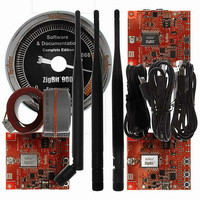
MNZB-DKC-900
Description
KIT DEV ZIGBIT 900 COMPLETE 1YR
Manufacturer
MeshNetics
Type
802.15.4/Zigbeer
Datasheet
1.MNZB-EVB-900-B0.pdf
(56 pages)
Specifications of MNZB-DKC-900
Frequency
868MHz, 915MHz
For Use With/related Products
MNZB-900-B0
Lead Free Status / RoHS Status
Lead free / RoHS Compliant
Other names
758-1009


© 2008 MeshNetics
2.3.2. Buttons, Switches and LEDs
Jumper position
J1 is open
Table 6. J2 jumper settings: ZigBit 900 power source
Jumper position
J2 bridges POWER pin and BAT pin
J2 bridges POWER pin and DC/DC
pin
Table 7. J3 jumper settings: Serial/USB selection
Jumper position
J3 bridges central pin and RS-232
pin
J3 bridges central pin and USB pin
IMPORTANT NOTES:
Any other position of jumpers J2 and J3 or their omission may cause permanent
damage of the hardware.
Powering the board without J1 jumper and ammeter connection between clamps CM+ and
CM- may cause a permanent damage of the hardware.
When making connection to the PC’s serial port through the Expansion slot consider the
pinout as indicated below in Table 8.
Table 8. Serial interface pinout
Signal
RXD
TXD
CTS
RTS
GND
The board includes 2 buttons, 3 DIP switches, one Reset button that generates a
hardware reset signal, 3 software-defined LEDs (green, yellow and red) and a LED
indicating powering the board from the USB. Any of onboard buttons, DIP switches and
LEDs can be controlled by an embedded application running on a ZigBit 900.
Z I G B I T ™ 9 0 0 D E V E L O P M E N T K I T 1 . 3
Expansion slot pins
4: UART_RXD
2: UART_TXD
3: UART_CTS
1: UART_RTS
5, 6, 15, 19, 20: GND
Description
ZigBit 900 is powered by primary source (battery,
USB or AC/DC adapter).
ZigBit 900 is powered by 3.6 V internal voltage
regulator.
Description
The board will use serial port (available in the
Expansion slot) for connection to the host.
The board will use USB for connection to the host.
Description
In this position, the ZigBit 900 module is not
powered while remaining parts of the board are
powered. This position is used to measure current
consumption of the ZigBit 900 module (see
Section 3.8).
Serial port pins
(PC side)
2
3
8
7
5
U S E R ’ S G U I D E
Page 19/56
Related parts for MNZB-DKC-900
Image
Part Number
Description
Manufacturer
Datasheet
Request
R

Part Number:
Description:
KIT DEV ZIGBIT 2.4GHZ COMPLETE
Manufacturer:
MeshNetics
Datasheet:


Part Number:
Description:
MOD 802.15.4/ZIGB 2.4GHZ RF PORT
Manufacturer:
MeshNetics
Datasheet:

Part Number:
Description:
BOARD EVAL FOR MNZB-900-B0 W/ANT
Manufacturer:
MeshNetics
Datasheet:

Part Number:
Description:
BOARD EVAL MNZB-A24-UFL W/RP-SMA
Manufacturer:
MeshNetics


Part Number:
Description:
BOARD DEV 802.15.4/ZIGB PCB ANT
Manufacturer:
MeshNetics
Datasheet:

Part Number:
Description:
BOARD DEV 802.15.4/ZIGB CHIP ANT
Manufacturer:
MeshNetics
Datasheet:

Part Number:
Description:
BOARD DEV 802.15.4/ZIGB SMA CONN
Manufacturer:
MeshNetics
Datasheet:
Part Number:
Description:
KIT DEV ZIGBIT 2.4GHZ LITE 45DAY
Manufacturer:
MeshNetics
Datasheet:

Part Number:
Description:
KIT DEV ZIGBIT 900 LITE 45DAYS
Manufacturer:
MeshNetics
Datasheet:


Part Number:
Description:
MOD 802.15.4/ZIGB 2.4GHZ CHIPANT
Manufacturer:
MeshNetics
Datasheet: