ADXL202JE Analog Devices Inc, ADXL202JE Datasheet - Page 10
ADXL202JE
Manufacturer Part Number
ADXL202JE
Description
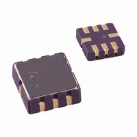
IC ACCELEROMETER LP 8-CLCC
Manufacturer
Analog Devices Inc
Datasheet
1.ADXL202EB.pdf
(12 pages)
Specifications of ADXL202JE
Axis
X, Y
Acceleration Range
±2g
Sensitivity
312mV/g
Voltage - Supply
3 V ~ 5.5 V
Output Type
Analog
Bandwidth
6kHz
Mounting Type
Surface Mount
Package / Case
8-CLCC
Lead Free Status / RoHS Status
Lead free / RoHS Compliant
Interface
-
Available stocks
Company
Part Number
Manufacturer
Quantity
Price
Company:

Part Number:
ADXL202JE
Manufacturer:
MITSUBISHI
Quantity:
23
Company:
Part Number:
ADXL202JE
Manufacturer:
ADI
Quantity:
717
Part Number:
ADXL202JE
Manufacturer:
ADI/亚德诺
Quantity:
20 000


ADXL202E
MICROCOMPUTER INTERFACES
The ADXL202E is specifically designed to work with low-cost
microcontrollers. Specific code sets, reference designs, and applica-
tion notes are available from the factory. This section will outline a
general design procedure and discuss the various trade-offs that
need to be considered.
The designer should have some idea of the required performance
of the system in terms of:
Resolution: the smallest signal change that needs to be detected.
Bandwidth: the highest frequency that needs to be detected.
Acquisition Time: the time that will be available to acquire the signal
on each axis.
These requirements will help to determine the accelerometer band-
width, the speed of the microcontroller clock and the length of
the T2 period.
When selecting a microcontroller it is helpful to have a counter
timer port available. The microcontroller should have provisions
for software calibration. While the ADXL202E is a highly accurate
accelerometer, it has a wide tolerance for initial offset. The easi-
est way to null this offset is with a calibration factor saved on the
microcontroller or by a user calibration for zero g. In the case
where the offset is calibrated during manufacture, there are several
options, including external EEPROM and microcontrollers with
“one-time programmable” features.
DESIGN TRADE-OFFS FOR SELECTING FILTER
CHARACTERISTICS: THE NOISE/BW TRADE-OFF
The accelerometer bandwidth selected will determine the measure-
ment resolution (smallest detectable acceleration). Filtering can be
used to lower the noise floor and improve the resolution of the
accelerometer. Resolution is dependent on both the analog filter
bandwidth at X
controller counter.
The analog output of the ADXL202E has a typical bandwidth
of 5 kHz, while the duty cycle modulators’ bandwidth is 500 Hz.
The user must filter the signal at this point to limit aliasing
errors. To minimize DCM errors the analog bandwidth should be
less than 1/10 the DCM frequency. Analog bandwidth may be
increased to up to 1/2 the DCM frequency in many applications.
This will result in greater dynamic error generated at the DCM.
The analog bandwidth may be further decreased to reduce noise
and improve resolution. The ADXL202E noise has the character-
istics of white Gaussian noise that contributes equally at all
frequencies and is described in terms of µg per root Hz; i.e., the
noise is proportional to the square root of the bandwidth of the
accelerometer. It is recommended that the user limit bandwidth to
the lowest frequency needed by the application, to maximize the
resolution and dynamic range of the accelerometer.
FILT
and Y
FILT
and on the speed of the micro-
With the single pole roll-off characteristic, the typical noise of
the ADXL202E is determined by the following equation:
At 100 Hz the noise will be:
Often the peak value of the noise is desired. Peak-to-peak noise
can only be estimated by statistical methods. Table III is useful
for estimating the probabilities of exceeding various peak values,
given the rms value.
The peak-to-peak noise value will give the best estimate of the
uncertainty in a single measurement.
Table IV gives typical noise output of the ADXL202E for various
C
Bandwidth
10 Hz
50 Hz
100 Hz
200 Hz
500 Hz
CHOOSING T2 AND COUNTER FREQUENCY: DESIGN
TRADE-OFFS
The noise level is one determinant of accelerometer resolution.
The second relates to the measurement resolution of the counter
when decoding the duty cycle output.
The ADXL202E’s duty cycle converter has a resolution of
approximately 14 bits; better resolution than the accelerometer
itself. The actual resolution of the acceleration signal is, how-
ever, limited by the time resolution of the counting devices used
to decode the duty cycle. The faster the counter clock, the higher
the resolution of the duty cycle and the shorter the T2 period
can be for a given resolution. The following table shows some of
the trade-offs. It is important to note that this is the resolution
due to the microprocessors’ counter. It is probable that the
accelerometer’s noise floor may set the lower limit on the resolu-
tion, as discussed in the previous section.
X
Noise rms
and C
Nominal Peak-to-Peak
Value
2.0 × rms
4.0 × rms
6.0 × rms
8.0 × rms
Table IV. Filter Capacitor Selection, C
( )
Table III. Estimation of Peak-to-Peak Noise
Y
Noise rms
values.
=
C
0.47 µF
0.10 µF
0.05 µF
0.027 µF 3.6 mg
0.01 µF
( )
(
X
200
, C
Y
=
µ /
g
(
200
rms Noise
0.8 mg
1.8 mg
2.5 mg
5.7 mg
Hz
µ /
g
)
×
% of Time that Noise
Will Exceed Nominal
Peak-to-Peak Value
32%
4.6%
0.27%
0.006%
Hz
100
)
×
Peak-to-Peak Noise
Estimate 95%
Probability (rms
3.2 mg
7.2 mg
10.1 mg
14.3 mg
22.6 mg
(
×
BW
( )
1 6
.
X
×
and C
=
1 6
.
2 53
)
.
Y
mg
4)
Related parts for ADXL202JE
Image
Part Number
Description
Manufacturer
Datasheet
Request
R

Part Number:
Description:
±1.7g Dual-Axis IMEMS Accelerometer Evaluation Board
Manufacturer:
Analog Devices Inc
Datasheet:

Part Number:
Description:
Inertial Sensor Evaluation System
Manufacturer:
Analog Devices Inc
Datasheet:
Part Number:
Description:
Manufacturer:
Analog Devices Inc
Datasheet:
Part Number:
Description:
Manufacturer:
Analog Devices Inc
Datasheet:
Part Number:
Description:
Manufacturer:
Analog Devices Inc
Datasheet:
Part Number:
Description:
Manufacturer:
Analog Devices Inc
Datasheet:
Part Number:
Description:
Manufacturer:
Analog Devices Inc
Datasheet:
Part Number:
Description:
Manufacturer:
Analog Devices Inc
Datasheet:
Part Number:
Description:
Manufacturer:
Analog Devices Inc
Datasheet:
Part Number:
Description:
Manufacturer:
Analog Devices Inc
Datasheet:
Part Number:
Description:
Manufacturer:
Analog Devices Inc
Datasheet:
Part Number:
Description:
Manufacturer:
Analog Devices Inc
Datasheet:
Part Number:
Description:
Manufacturer:
Analog Devices Inc
Datasheet: