ADXL202JE Analog Devices Inc, ADXL202JE Datasheet - Page 11
ADXL202JE
Manufacturer Part Number
ADXL202JE
Description
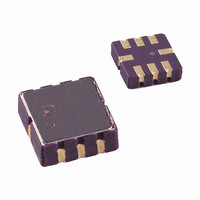
IC ACCELEROMETER LP 8-CLCC
Manufacturer
Analog Devices Inc
Datasheet
1.ADXL202EB.pdf
(12 pages)
Specifications of ADXL202JE
Axis
X, Y
Acceleration Range
±2g
Sensitivity
312mV/g
Voltage - Supply
3 V ~ 5.5 V
Output Type
Analog
Bandwidth
6kHz
Mounting Type
Surface Mount
Package / Case
8-CLCC
Lead Free Status / RoHS Status
Lead free / RoHS Compliant
Interface
-
Available stocks
Company
Part Number
Manufacturer
Quantity
Price
Company:

Part Number:
ADXL202JE
Manufacturer:
MITSUBISHI
Quantity:
23
Company:
Part Number:
ADXL202JE
Manufacturer:
ADI
Quantity:
717
Part Number:
ADXL202JE
Manufacturer:
ADI/亚德诺
Quantity:
20 000


Table V. Trade-Offs Between Microcontroller Counter Rate,
T2 Period, and Resolution of Duty Cycle Modulator
T2 (ms) (k ) Rate
1.0
1.0
1.0
5.0
5.0
5.0
10.0
10.0
10.0
STRATEGIES FOR USING THE DUTY CYCLE OUTPUT
WITH MICROCONTROLLERS
Application notes outlining various strategies for using the duty
cycle output with low cost microcontrollers are available from
the factory.
USING THE ADXL202E AS A DUAL-AXIS TILT SENSOR
One of the most popular applications of the ADXL202E is tilt
measurement. An accelerometer uses the force of gravity as an
input vector to determine orientation of an object in space.
An accelerometer is most sensitive to tilt when its sensitive axis
is perpendicular to the force of gravity, i.e., parallel to the earth’s
surface. At this orientation its sensitivity to changes in tilt is high-
est. When the accelerometer is oriented on axis to gravity, i.e.,
near its +1 g or –1 g reading, the change in output acceleration
per degree of tilt is negligible. When the accelerometer is perpen-
dicular to gravity, its output will change nearly 17.5 mg per degree
of tilt, but at 45° degrees it is changing only at 12.2 mg per
degree and resolution declines. The following table illustrates
the changes in the X and Y axes as the device is tilted ± 90°
through gravity.
X Axis
Orientation
to Horizon ( )
–90
–75
–60
–45
–30
–15
15
30
45
60
75
90
0
R
124
124
124
625
625
625
1250 100
1250 100
1250 100
SET
X
ADXL202E Clock
Sample
1000
1000
1000
200
200
200
BOTTOM VIEW
X Output (g)
–1.000
–0.966
–0.866
–0.707
–0.500
–0.259
0.000
0.259
0.500
0.707
0.866
0.966
1.000
X Output
Counter-
Rate
(MHz)
2.0
1.0
0.5
2.0
1.0
0.5
2.0
1.0
0.5
Y
Degree of
Tilt (mg)
per
–0.2
12.2
15.0
16.8
17.5
16.9
15.2
12.4
4.4
8.6
8.9
4.7
0.2
+90
–90
Counts
per T2
Cycle
2000
1000
500
10000
5000
2500
20000
10000
5000
Y Output (g)
0
0.000
0.259
0.500
0.707
0.866
0.966
1.000
0.966
0.866
0.707
0.500
0.259
0.000
Counts Resolution
per g
250
125
62.5
1250
625
312.5
2500
1250
625
1g
Y Output (g)
(mg)
4.0
8.0
16.0
0.8
1.6
3.2
0.4
0.8
1.6
Degree of
Tilt (mg)
–12.2
–15.0
–16.8
–17.5
per
17.5
16.9
15.2
12.4
–4.4
–8.6
8.9
4.7
0.2
A DUAL AXIS TILT SENSOR: CONVERTING
ACCELERATION TO TILT
When the accelerometer is oriented so both its X and Y axes are
parallel to the earth’s surface it can be used as a two axis tilt sensor
with a roll and a pitch axis. Once the output signal from the
accelerometer has been converted to an acceleration that varies
between –1 g and +1 g, the output tilt in degrees is calculated as
follows:
Be sure to account for overranges. It is possible for the acceler-
ometers to output a signal greater than ± 1 g due to vibration,
shock or other accelerations.
MEASURING 360 OF TILT
It is possible to measure a full 360° of orientation through gravity
by using two accelerometers oriented perpendicular to one another
(see Figure 5). When one sensor is reading a maximum change
in output per degree, the other is at its minimum.
USING THE ANALOG OUTPUT
The ADXL202E was specifically designed for use with its digital
outputs, but has provisions to provide analog outputs as well.
Duty Cycle Filtering
An analog output can be reconstructed by filtering the duty cycle
output. This technique requires only passive components. The
duty cycle period (T2) should be set to <1 ms. An RC filter with a
3 dB point at least a factor of >10 less than the duty cycle fre-
quency is connected to the duty cycle output. The filter resistor
should be no less than 100 kΩ to prevent loading of the output
stage. The analog output signal will be ratiometric to the supply
voltage. The advantage of this method is an output scale factor of
approximately double the analog output. Its disadvantage is that
the frequency response will be lower than when using the X
Y
X
The second method is to use the analog output present at the
X
output impedance and are not designed to drive a load directly.
An op amp follower may be required to buffer this pin. The
advantage of this method is that the full 5 kHz bandwidth of the
accelerometer is available to the user. A capacitor still must be
added at this point for filtering. The duty cycle converter should
be kept running by using R
ometer offset and sensitivity are ratiometric to the supply voltage.
The offset and sensitivity are nominally:
0 g Offset = V
ADXL202E Sensitivity = (60 mV × V
FILT
FILT
FILT
, Y
output.
°
and Y
FILT
Output
FILT
DD
X
/2
pin. Unfortunately, these pins have a 32 kΩ
Pitch = ASIN (Ax/1 g)
Roll = ASIN (Ay/1 g)
SET
Y
<10 MΩ. Note that the acceler-
S
360 OF TILT
)/g
ADXL202E
1g
FILT
,
Related parts for ADXL202JE
Image
Part Number
Description
Manufacturer
Datasheet
Request
R

Part Number:
Description:
±1.7g Dual-Axis IMEMS Accelerometer Evaluation Board
Manufacturer:
Analog Devices Inc
Datasheet:

Part Number:
Description:
Inertial Sensor Evaluation System
Manufacturer:
Analog Devices Inc
Datasheet:
Part Number:
Description:
Manufacturer:
Analog Devices Inc
Datasheet:
Part Number:
Description:
Manufacturer:
Analog Devices Inc
Datasheet:
Part Number:
Description:
Manufacturer:
Analog Devices Inc
Datasheet:
Part Number:
Description:
Manufacturer:
Analog Devices Inc
Datasheet:
Part Number:
Description:
Manufacturer:
Analog Devices Inc
Datasheet:
Part Number:
Description:
Manufacturer:
Analog Devices Inc
Datasheet:
Part Number:
Description:
Manufacturer:
Analog Devices Inc
Datasheet:
Part Number:
Description:
Manufacturer:
Analog Devices Inc
Datasheet:
Part Number:
Description:
Manufacturer:
Analog Devices Inc
Datasheet:
Part Number:
Description:
Manufacturer:
Analog Devices Inc
Datasheet:
Part Number:
Description:
Manufacturer:
Analog Devices Inc
Datasheet: