ADXL202JE Analog Devices Inc, ADXL202JE Datasheet - Page 9
ADXL202JE
Manufacturer Part Number
ADXL202JE
Description
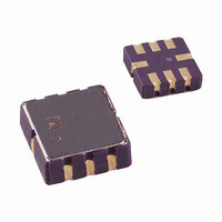
IC ACCELEROMETER LP 8-CLCC
Manufacturer
Analog Devices Inc
Datasheet
1.ADXL202EB.pdf
(12 pages)
Specifications of ADXL202JE
Axis
X, Y
Acceleration Range
±2g
Sensitivity
312mV/g
Voltage - Supply
3 V ~ 5.5 V
Output Type
Analog
Bandwidth
6kHz
Mounting Type
Surface Mount
Package / Case
8-CLCC
Lead Free Status / RoHS Status
Lead free / RoHS Compliant
Interface
-
Available stocks
Company
Part Number
Manufacturer
Quantity
Price
Company:

Part Number:
ADXL202JE
Manufacturer:
MITSUBISHI
Quantity:
23
Company:
Part Number:
ADXL202JE
Manufacturer:
ADI
Quantity:
717
Part Number:
ADXL202JE
Manufacturer:
ADI/亚德诺
Quantity:
20 000


DESIGN PROCEDURE FOR THE ADXL202E
The design procedure for using the ADXL202E with a duty cycle
output involves selecting a duty cycle period and a filter capacitor.
A proper design will take into account the application requirements
for bandwidth, signal resolution and acquisition time, as discussed
in the following sections.
Decoupling Capacitor C
A 0.1 µF capacitor is recommended from V
supply decoupling.
ST
The ST pin controls the self-test feature. When this pin is set to
V
eter. The resulting movement of the beam allows the user to test if
the accelerometer is functional. The typical change in output will
be 10% at the duty cycle outputs (corresponding to 800 mg).
This pin may be left open circuit or connected to common in
normal use.
Duty Cycle Decoding
The ADXL202E’s digital output is a duty cycle modulator.
Acceleration is proportional to the ratio T1/T2. The nominal
output of the ADXL202E is:
These nominal values are affected by the initial tolerance of the
device including zero g offset error and sensitivity error.
T2 does not have to be measured for every measurement cycle.
It need only be updated to account for changes due to tempera-
ture, (a relatively slow process). Since the T2 time period is shared
by both X and Y channels, it is necessary only to measure it on
one channel of the ADXL202E. Decoding algorithms for various
microcontrollers have been developed. Consult the appropriate
Application Note.
DD
C
DC
, an electrostatic force is exerted on the beam of the accelerom-
Scale factor is 12.5% Duty Cycle Change per g
OSCILLATOR
3V TO 5.25V
X SENSOR
Y SENSOR
COM
V
DD
DEMOD
DEMOD
0 g = 50% Duty Cycle
ADXL202E
DC
R
32k
R
32k
FILT
FILT
C
X
X
Y
FILT
FILT
C
Y
ANALOG
T1
CYCLE
(ADC)
DUTY
DD
TO
SELF-TEST
T2
A(g) = (T1/T2 – 0.5)/12.5%
0g = 50% DUTY CYCLE
T2 = R
R
T2
to COM for power
SET
SET
X
Y
/125M
OUT
OUT
O
C
U
N
T
E
R
P
Setting the Bandwidth Using C
The ADXL202E has provisions for bandlimiting the X
Y
low-pass filtering for antialiasing and noise reduction. The equa-
tion for the 3 dB bandwidth is:
or, more simply, F
The tolerance of the internal resistor (R
much as ± 15% of its nominal value of 32 kΩ; so the bandwidth
will vary accordingly. A minimum capacitance of 1000 pF for
C
Setting the DCM Period with R
The period of the DCM output is set for both channels by a single
resistor from R
A 125 kΩ resistor will set the duty cycle repetition rate to approxi-
mately 1 kHz, or 1 ms. The device is designed to operate at duty
cycle periods between 0.5 ms and 10 ms.
Note that the R
analog output is desired. Use an R
and 2 MΩ when taking the output from X
resistor should be place close to the T2 Pin to minimize parasitic
capacitance at this node.
Selecting the Right Accelerometer
For most tilt sensing applications the ADXL202E is the most
appropriate accelerometer. Its higher sensitivity (12.5%/g) allows
the user to use a lower speed counter for PWM decoding while
maintaining high resolution. The ADXL210 should be used in
applications where accelerations of greater than ±2 g are expected.
FILT
(X, Y)
pins. Capacitors must be added at these pins to implement
is required in all cases.
Table I. Filter Capacitor Selection, C
Bandwidth
10 Hz
50 Hz
100 Hz
200 Hz
500 Hz
5 kHz
Table II. Resistor Values to Set T2
SET
T2
1 ms
2 ms
5 ms
10 ms
SET
F
–3 dB
to ground. The equation for the period is:
–3 dB
should always be included, even if only an
=
=
(
T 2 =
C
2 π (32 kΩ) × C(x, y)
5 µF
(X ,Y )
125 MΩ
R
X
SET
SET
and C
1
SET
(Ω)
FILT
Capacitor
Value
0.47 µF
0.10 µF
0.05 µF
0.027 µF
0.01 µF
0.001 µF
R
125 kΩ
250 kΩ
625 kΩ
1.25 MΩ
value between 500 kΩ
FILT
Y
SET
), can vary typically as
ADXL202E
or Y
)
X
FILT
and C
. The R
FILT
Y
and
SET
Related parts for ADXL202JE
Image
Part Number
Description
Manufacturer
Datasheet
Request
R

Part Number:
Description:
±1.7g Dual-Axis IMEMS Accelerometer Evaluation Board
Manufacturer:
Analog Devices Inc
Datasheet:

Part Number:
Description:
Inertial Sensor Evaluation System
Manufacturer:
Analog Devices Inc
Datasheet:
Part Number:
Description:
Manufacturer:
Analog Devices Inc
Datasheet:
Part Number:
Description:
Manufacturer:
Analog Devices Inc
Datasheet:
Part Number:
Description:
Manufacturer:
Analog Devices Inc
Datasheet:
Part Number:
Description:
Manufacturer:
Analog Devices Inc
Datasheet:
Part Number:
Description:
Manufacturer:
Analog Devices Inc
Datasheet:
Part Number:
Description:
Manufacturer:
Analog Devices Inc
Datasheet:
Part Number:
Description:
Manufacturer:
Analog Devices Inc
Datasheet:
Part Number:
Description:
Manufacturer:
Analog Devices Inc
Datasheet:
Part Number:
Description:
Manufacturer:
Analog Devices Inc
Datasheet:
Part Number:
Description:
Manufacturer:
Analog Devices Inc
Datasheet:
Part Number:
Description:
Manufacturer:
Analog Devices Inc
Datasheet: