ADXL202JE Analog Devices Inc, ADXL202JE Datasheet - Page 8
ADXL202JE
Manufacturer Part Number
ADXL202JE
Description
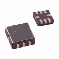
IC ACCELEROMETER LP 8-CLCC
Manufacturer
Analog Devices Inc
Datasheet
1.ADXL202EB.pdf
(12 pages)
Specifications of ADXL202JE
Axis
X, Y
Acceleration Range
±2g
Sensitivity
312mV/g
Voltage - Supply
3 V ~ 5.5 V
Output Type
Analog
Bandwidth
6kHz
Mounting Type
Surface Mount
Package / Case
8-CLCC
Lead Free Status / RoHS Status
Lead free / RoHS Compliant
Interface
-
Available stocks
Company
Part Number
Manufacturer
Quantity
Price
Company:

Part Number:
ADXL202JE
Manufacturer:
MITSUBISHI
Quantity:
23
Company:
Part Number:
ADXL202JE
Manufacturer:
ADI
Quantity:
717
Part Number:
ADXL202JE
Manufacturer:
ADI/亚德诺
Quantity:
20 000


ADXL202E
DEFINITIONS
T1
T2
Duty Cycle Ratio of the “on” time (T1) of the cycle to the total
Pulsewidth
THEORY OF OPERATION
The ADXL202E is a complete, dual-axis acceleration measurement
system on a single monolithic IC. It contains a polysilicon surface-
micromachined sensor and signal conditioning circuitry to imple-
ment an open loop acceleration measurement architecture. For
each axis, an output circuit converts the analog signal to a duty
cycle modulated (DCM) digital signal that can be decoded with
a counter/timer port on a microprocessor. The ADXL202E is
capable of measuring both positive and negative accelerations to
at least ± 2 g. The accelerometer can measure static acceleration
forces such as gravity, allowing it to be used as a tilt sensor.
The sensor is a surface micromachined polysilicon structure
built on top of the silicon wafer. Polysilicon springs suspend
the structure over the surface of the wafer and provide a resistance
against acceleration forces. Deflection of the structure is measured
using a differential capacitor that consists of independent fixed
plates and central plates attached to the moving mass. The fixed
plates are driven by 180° out of phase square waves. An accelera-
tion will deflect the beam and unbalance the differential capacitor,
resulting in an output square wave whose amplitude is propor-
tional to acceleration. Phase sensitive demodulation techniques are
then used to rectify the signal and determine the direction of
the acceleration.
The output of the demodulator drives a duty cycle modulator
(DCM) stage through a 32 kΩ resistor. At this point a pin is
available on each channel to allow the user to set the signal band-
width of the device by adding a capacitor. This filtering improves
measurement resolution and helps prevent aliasing.
After being low-pass filtered, the analog signal is converted to a
duty cycle modulated signal by the DCM stage. A single resistor
sets the period for a complete cycle (T2), which can be set between
0.5 ms and 10 ms (see Figure 12). A 0 g acceleration produces a
Length of the “on” portion of the cycle.
Length of the total cycle.
Time period of the “on” pulse. Defined as T1 for
cycle (T2). Defined as T1/T2 for the ADXL202E/
ADXL210.
the ADXL202E/ADXL210.
1.06
1.04
1.02
1.00
0.98
0.96
0.94
–45
–30
–15
0
TEMPERATURE – C
15
nominally 50% duty cycle. The acceleration signal can be deter-
mined by measuring the length of the T1 and T2 pulses with
a counter/timer or with a polling loop using a low cost micro-
controller.
An analog output voltage can be obtained either by buffering the
signal from the X
signal through an RC filter to reconstruct the dc value.
The ADXL202E will operate with supply voltages as low as 3.0 V
or as high as 5.25 V.
APPLICATIONS
POWER SUPPLY DECOUPLING
For most applications a single 0.1 µF capacitor, C
adequately decouple the accelerometer from signal and noise
on the power supply. However, in some cases, especially where
digital devices such as microcontrollers share the same power
supply, digital noise on the supply may cause interference on
the ADXL202E output. This may be observed as a slowly
undulating fluctuation of voltage at X
decoupling is needed, a 100 Ω (or smaller) resistor or ferrite
beads, may be inserted in the supply line of the ADXL202E.
30
45
V
DD
60
100
75
FILT
FERRITE BEAD
R
C
SET
DC
and Y
A(g) = (T1/T2 – 0.5)/12.5%
0g = 50% DUTY CYCLE
T2(s) = R
90
T1
FILT
V
COM
ST
T2
SET
DD
ADXL202E
( )/125M
pin, or by passing the duty cycle
T2
FILT
X
Y
X
Y
OUT
OUT
FILT
FILT
and Y
FILT
Y
FILT
. If additional
DC
X
FILT
, will
Related parts for ADXL202JE
Image
Part Number
Description
Manufacturer
Datasheet
Request
R

Part Number:
Description:
±1.7g Dual-Axis IMEMS Accelerometer Evaluation Board
Manufacturer:
Analog Devices Inc
Datasheet:

Part Number:
Description:
Inertial Sensor Evaluation System
Manufacturer:
Analog Devices Inc
Datasheet:
Part Number:
Description:
Manufacturer:
Analog Devices Inc
Datasheet:
Part Number:
Description:
Manufacturer:
Analog Devices Inc
Datasheet:
Part Number:
Description:
Manufacturer:
Analog Devices Inc
Datasheet:
Part Number:
Description:
Manufacturer:
Analog Devices Inc
Datasheet:
Part Number:
Description:
Manufacturer:
Analog Devices Inc
Datasheet:
Part Number:
Description:
Manufacturer:
Analog Devices Inc
Datasheet:
Part Number:
Description:
Manufacturer:
Analog Devices Inc
Datasheet:
Part Number:
Description:
Manufacturer:
Analog Devices Inc
Datasheet:
Part Number:
Description:
Manufacturer:
Analog Devices Inc
Datasheet:
Part Number:
Description:
Manufacturer:
Analog Devices Inc
Datasheet:
Part Number:
Description:
Manufacturer:
Analog Devices Inc
Datasheet: