ADXL202JE Analog Devices Inc, ADXL202JE Datasheet - Page 2
ADXL202JE
Manufacturer Part Number
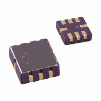
ADXL202JE
Description
IC ACCELEROMETER LP 8-CLCC
Manufacturer
Analog Devices Inc
Datasheet
1.ADXL202EB.pdf
(12 pages)
Specifications of ADXL202JE
Axis
X, Y
Acceleration Range
±2g
Sensitivity
312mV/g
Voltage - Supply
3 V ~ 5.5 V
Output Type
Analog
Bandwidth
6kHz
Mounting Type
Surface Mount
Package / Case
8-CLCC
Lead Free Status / RoHS Status
Lead free / RoHS Compliant
Interface
-
Available stocks
Company
Part Number
Manufacturer
Quantity
Price
Company:

Part Number:
ADXL202JE
Manufacturer:
MITSUBISHI
Quantity:
23
Company:
Part Number:
ADXL202JE
Manufacturer:
ADI
Quantity:
717
Part Number:
ADXL202JE
Manufacturer:
ADI/亚德诺
Quantity:
20 000


ADXL202E–SPECIFICATIONS
Parameter
SENSOR INPUT
SENSITIVITY
ZERO g BIAS LEVEL
NOISE PERFORMANCE
FREQUENCY RESPONSE
FILTER
SELF-TEST
DUTY CYCLE OUTPUT STAGE
POWER SUPPLY
TEMPERATURE RANGE
NOTES
1
2
3
4
5
Specifications subject to change without notice.
Typical Performance Characteristics.
Guaranteed by measurement of initial offset and sensitivity.
Alignment error is specified as the angle between the true and indicated axis of sensitivity (see TPC 15).
Cross-axis sensitivity is the algebraic sum of the alignment and the inherent sensitivity errors.
Defined as the output change from ambient to maximum temperature or ambient to minimum temperature.
Sensitivity X
Sensitivity X
Temperature Drift
0 g Duty Cycle
0 g Duty Cycle
0 g Voltage X
0 g Voltage X
0 g Duty Cycle vs. Supply
0 g Offset vs. Temperature
Noise Density
3 dB Bandwidth
Sensor Resonant Frequency
R
Minimum Capacitance
Duty Cycle Change
F
Output High Voltage
Output Low Voltage
T2 Drift vs. Temperature
Rise/Fall Time
Operating Voltage Range
Quiescent Supply Current
Turn-On Time
Specified Performance AE
Operating Range
Measurement Range
Nonlinearity
Alignment Error
Alignment Error
Cross-Axis Sensitivity
Duty Cycle per g
Duty Cycle per g
FILT
SET
Tolerance
FILT
FILT
FILT
FILT
, Y
, Y
3
, Y
, Y
5
FILT
FILT
FILT
FILT
2
4
5
Conditions
Each Axis
Best Fit Straight Line
X Sensor to Y Sensor
Each Axis
T1/T2, V
T1/T2, V
V
V
Delta from 25 C
Each Axis
T1/T2, V
T1/T2, V
V
V
Delta from 25 C
@ 25 C
At Pins X
32 kΩ Nominal
At Pins X
Self-Test “0” to “1”
R
I = 25 µA
I = 25 µA
C
DD
DD
DD
DD
SET
FILT
= 5 V
= 3 V
= 5 V
= 3 V
= 125 kΩ
in µF
DD
DD
DD
DD
FILT
FILT
= 5 V
= 3 V
= 5 V
= 3 V
, Y
, Y
FILT
FILT
(T
Acceleration = 0 g , unless otherwise noted.)
TPC
Graph
X
X
X
X
X
X
X
X
X
X
X
X
X
X
A
= T
1
MIN
to T
Min
± 2
10.5
9.0
265
140
34
31
2.1
1.2
1000
0.7
V
3
0
S
160
– 200 mV
MAX
ADXL202JE
, T
C
A
FILT
= 25 C for J Grade only, V
Typ
0.2
± 1
0.01
± 2
12.5
11
312
167
± 0.5
50
50
2.5
1.5
1.0
2.0
200
6
10
± 15
10
50
200
0.6
+ 0.3
Max
14.5
13.0
360
195
66
69
2.9
1.8
4.0
1.3
200
5.25
1.0
70
Min
± 2
10
8.5
250
140
30
31
2.0
1.2
1000
0.7
V
3.0
–40
–40
S
– 200 mV
160
DD
ADXL202AE
= 5 V, R
C
Typ
0.2
± 1
0.01
± 2
12.5
11
312
167
± 0.5
50
50
2.5
1.5
1.0
2.0
200
6
10
± 15
10
50
200
0.6
FILT
+ 0.3
SET
= 125 k ,
Max
15
13.5
375
200
70
69
3.0
1.8
4.0
1000
1.3
200
5.25
1.0
+85
+85
Unit
% of FS
%/g
mA
g
Degrees
Degrees
%
%/g
mV/g
mV/g
%
%
%
V
V
%/V
mg/ C
µg√Hz rms
kHz
kHz
%
pF
%
kHz
V
mV
ppm/ C
ns
V
ms
C
C
Related parts for ADXL202JE
Image
Part Number
Description
Manufacturer
Datasheet
Request
R

Part Number:
Description:
±1.7g Dual-Axis IMEMS Accelerometer Evaluation Board
Manufacturer:
Analog Devices Inc
Datasheet:

Part Number:
Description:
Inertial Sensor Evaluation System
Manufacturer:
Analog Devices Inc
Datasheet:
Part Number:
Description:
Manufacturer:
Analog Devices Inc
Datasheet:
Part Number:
Description:
Manufacturer:
Analog Devices Inc
Datasheet:
Part Number:
Description:
Manufacturer:
Analog Devices Inc
Datasheet:
Part Number:
Description:
Manufacturer:
Analog Devices Inc
Datasheet:
Part Number:
Description:
Manufacturer:
Analog Devices Inc
Datasheet:
Part Number:
Description:
Manufacturer:
Analog Devices Inc
Datasheet:
Part Number:
Description:
Manufacturer:
Analog Devices Inc
Datasheet:
Part Number:
Description:
Manufacturer:
Analog Devices Inc
Datasheet:
Part Number:
Description:
Manufacturer:
Analog Devices Inc
Datasheet:
Part Number:
Description:
Manufacturer:
Analog Devices Inc
Datasheet:
Part Number:
Description:
Manufacturer:
Analog Devices Inc
Datasheet: