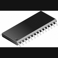
DS14C335MSA National Semiconductor, DS14C335MSA Datasheet - Page 5

DS14C335MSA
Manufacturer Part Number
DS14C335MSA
Description
IC, RS-232 TRANSCEIVER, 3.6V, SSOP-28
Manufacturer
National Semiconductor
Datasheet
1.DS14C335MSANOPB.pdf
(9 pages)
Specifications of DS14C335MSA
Device Type
Driver / Receiver
Ic Interface Type
RS232
No. Of Drivers
3
Supply Voltage Range
3V To 3.6V
Driver Case Style
SSOP
No. Of Pins
28
Operating Temperature Range
0°C To +70°C
Package
28SSOP-EIAJ
Data Transmission Topology
Point-to-Point
Interface Standards
EIA/TIA-232-E|V.28
Data Rate
0.128 Mbps
Function
Line Transmitter/Receiver
Number Of Receivers
5
Number Of Transmitters
3
Transmitter Signal Type
Single-Ended
Transmitter Communication Type
RS-232
Typical Single Supply Voltage
3.3 V
Lead Free Status / RoHS Status
Contains lead / RoHS non-compliant
Available stocks
Company
Part Number
Manufacturer
Quantity
Price
Company:
Part Number:
DS14C335MSA
Manufacturer:
ON
Quantity:
36
Company:
Part Number:
DS14C335MSA
Manufacturer:
NS
Quantity:
4 465
Company:
Part Number:
DS14C335MSA
Manufacturer:
NSC
Quantity:
1 898
Part Number:
DS14C335MSA
Manufacturer:
NS/国半
Quantity:
20 000
Company:
Part Number:
DS14C335MSA.
Manufacturer:
TI
Quantity:
21 727
Company:
Part Number:
DS14C335MSAX
Manufacturer:
NEC
Quantity:
29
Part Number:
DS14C335MSAX
Manufacturer:
NS/国半
Quantity:
20 000
Parameter Measurement Information
Pin Descriptions
V
V+ (Pin 1). Positive supply for TIA/EIA-232-E drivers. Rec-
ommended external capacitor — 0.47 µF (16V). This supply
is not intended to be loaded externally.
V− (Pin 25). Negative supply for TIA/EIA-232-E drivers.
Recommended external capacitor — 0.47 µF (16V). This
supply is not intended to be loaded externally.
C1+, C1− (Pins 6, 24). External capacitor connection pins.
Recommended capacitor — 0.47 µF (6.3V).
C2+, C2− (Pins 2, 4). External capacitor connection pins.
Recommended capacitor — 0.47 µF (16V).
CC
(Pin 3). Power supply pin for the device, +3.3V (
FIGURE 7. Receiver SHUTDOWN (SD) Delay Test Circuit
FIGURE 8. Receiver SHUTDOWN (SD) Delay Timing
FIGURE 6. Driver SHUTDOWN (SD) Delay Timing
±
0.3V).
5
(Continued)
C3+, C3− (Pins 28, 26). External capacitor connection pins.
Recommended capacitor — 0.47 µF (6.3V).
SHUTDOWN (SD) (Pin 23). A High on the SHUTDOWN pin
will lower the total I
low power state. In this mode receiver R5 remains active.
The SD pin should be driven or tied low (GND) to disable the
shutdown mode.
D
standard compatible.
D
TIA/ElA-232 -E levels.
IN
OUT
1–3 (Pins 7, 8, 9). Driver input pins are JEDEC 3.3V
1–3 (Pins 22, 21, 20). Driver output pins conform to
CC
current to less than 10 µA, providing a
01173409
01173408
01173410
www.national.com


