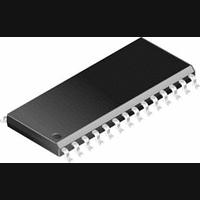
DS14C335MSA National Semiconductor, DS14C335MSA Datasheet - Page 6

DS14C335MSA
Manufacturer Part Number
DS14C335MSA
Description
IC, RS-232 TRANSCEIVER, 3.6V, SSOP-28
Manufacturer
National Semiconductor
Datasheet
1.DS14C335MSANOPB.pdf
(9 pages)
Specifications of DS14C335MSA
Device Type
Driver / Receiver
Ic Interface Type
RS232
No. Of Drivers
3
Supply Voltage Range
3V To 3.6V
Driver Case Style
SSOP
No. Of Pins
28
Operating Temperature Range
0°C To +70°C
Package
28SSOP-EIAJ
Data Transmission Topology
Point-to-Point
Interface Standards
EIA/TIA-232-E|V.28
Data Rate
0.128 Mbps
Function
Line Transmitter/Receiver
Number Of Receivers
5
Number Of Transmitters
3
Transmitter Signal Type
Single-Ended
Transmitter Communication Type
RS-232
Typical Single Supply Voltage
3.3 V
Lead Free Status / RoHS Status
Contains lead / RoHS non-compliant
Available stocks
Company
Part Number
Manufacturer
Quantity
Price
Company:
Part Number:
DS14C335MSA
Manufacturer:
ON
Quantity:
36
Company:
Part Number:
DS14C335MSA
Manufacturer:
NS
Quantity:
4 465
Company:
Part Number:
DS14C335MSA
Manufacturer:
NSC
Quantity:
1 898
Part Number:
DS14C335MSA
Manufacturer:
NS/国半
Quantity:
20 000
Company:
Part Number:
DS14C335MSA.
Manufacturer:
TI
Quantity:
21 727
Company:
Part Number:
DS14C335MSAX
Manufacturer:
NEC
Quantity:
29
Part Number:
DS14C335MSAX
Manufacturer:
NS/国半
Quantity:
20 000
www.national.com
Pin Descriptions
R
TIA/EIA-232-E input voltages (
hysteresis of TBD mV. Unused receiver input pins may be
left open. Internal input resistor (5 kΩ) pulls input LOW,
providing a failsafe HIGH output.
R
JEDEC 3.3V standard compatible.
GND (Pin 27). Ground Pin.
Application Information
9-PIN SERIAL PORT APPLICATION
In a typical Data Terminal Equipment (DTE) to Data Circuit-
Terminating Equipment (DCE) 9-pin de-facto interface imple-
mentation, 2 data lines and 6 control lines are required. The
MOUSE DRIVING
The DS14C335 was tested for drive current under the fol-
lowing mouse driving conditions:
Completion of the testing (performed by National’s Data
Transmission Applications Group and a major PC manufac-
EXTERNAL DC-DC CONVERTOR COMPONENTS
The DS14C335 with it’s unique DC-DC Convertor triples the
power supply voltage (3.0V) to +9.3V and then inverts it to a
−9V potential. This unique convertor ONLY requires 5 exter-
• Two driver outputs set at V
• One driver output set at V
• One receiver was used to accept data from the mouse
• Power Supply Voltage (V
IN
OUT
together (paralleled), sourcing current to supply the V+
terminal of the mouse electronics
V− terminal of the mouse electronics
1–5 (Pins 19, 18, 17, 16, 15). Receiver input pins accept
1–5 (Pins 10, 11, 12, 13, 14). Receiver output pins are
CC
OL
OH
(Continued)
±
): 3.0V to 3.6V
25V). Receivers guarantees
to sink the current from the
and their outputs were tied
FIGURE 9. Typical DTE Application
6
data lines are TXD and RXD and the control lines are RTS,
DTR, DSR, DCD, CTS and RI. The DS14C335 is a 3 x 5
Driver/Receiver and offers a single chip solution for the DTE
interface as shown in Figure 9.
Ring Indicator (RI) is used to inform the DTE that an incom-
ing call is coming from a remote DCE. When the DS14C335
is in SHUTDOWN (SD) mode, receiver five (R5) remains
active and monitors RI circuit. This active receiver (R5) alerts
the DTE to switch the DS14C335 from SHUTDOWN to
active mode.
turer) concluded that the DS14C335 and it’s DC-DC Conver-
tor supplied adequate drive capability to power a typical PC
mouse. The mouse tested was specified with the following
conditions:
Since driver current is limited, it is recommended that newer
lower power mice be specified for battery powered applica-
tions. Using older high power mice is wasteful of precious
battery charge.
nal surface mount 0.47 µF capacitors. The five identical
components were chosen to simplify PCB layout and the
procurement of components. The DS14C335’s DC-DC Con-
10 mA at +6V
5.0 mA at −6V
01173411


