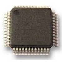
SC16C650BIB48 NXP Semiconductors, SC16C650BIB48 Datasheet - Page 45

SC16C650BIB48
Manufacturer Part Number
SC16C650BIB48
Description
UART, 32BYTE FIFO, 16C650, LQFP48
Manufacturer
NXP Semiconductors
Datasheet
1.SC16C650BIB48151.pdf
(48 pages)
Specifications of SC16C650BIB48
No. Of Channels
1
Data Rate
3Mbps
Supply Voltage Range
2.25V To 5.5V
Operating Temperature Range
-40°C To +85°C
Digital Ic Case Style
LQFP
No. Of Pins
48
Svhc
No SVHC (18-Jun-2010)
Operating
RoHS Compliant
Uart Features
Automatic Software/Hardware Flow Control, Programmable Xon/Xoff Characters
Rohs Compliant
Yes
Available stocks
Company
Part Number
Manufacturer
Quantity
Price
Company:
Part Number:
SC16C650BIB48,151
Manufacturer:
NXP Semiconductors
Quantity:
10 000
Company:
Part Number:
SC16C650BIB48151
Manufacturer:
NXP Semiconductors
Quantity:
135
NXP Semiconductors
Table 32.
SC16C650B_4
Product data sheet
Document ID
Modifications:
Revision history
Release date
•
•
•
•
•
•
•
•
Section 2
pins”, and added
Table 2 “Pin
– added (new)
– Description for signal DDIS changed from “DDIS is active (LOW) when the CPU is not reading
Section 6.8 “DMA
– 3
– added Remark
Section 7 “Register
– first paragraph: changed from “... for the fifteen SC16C650B internal registers.” to “... for the
Table 8 “SC16C650B internal
– descriptive text below table title moved to (new)
– removed shading from 9 table cells; added reference to
– deleted reference to
–
– added (new)
– added (new)
– MCR bit 2 changed from “OUT1” to “OUT1, OUT”
– MCR bit 3 changed from “OUT2, INT enable” to “OUT2”
Table 19 “Modem Control Register bits
– description of MCR[5]: removed references to IRQA pin
– description of MCR[5]: logic 0: changed from “enable active or 3-State interrupt output mode”
– description of MCR[5]: logic 1, second sentence changed from “Provides shared interrupts in
– description of MCR[3] re-written
– description of MCR[2] re-written
Table 25 “Reset state for
TXRDY and INT outputs
Table 26 “Limiting
– parameter description for symbol V
– parameter description for symbol T
– symbol for ‘total power dissipation per package” changed from “P
data. When active, DDIS can disable an external transceiver.” to “DDIS is active (LOW) when
the CPU is reading data. When inactive (HIGH), DDIS can disable an external transceiver.”
state of the RXRDY and TXRDY output pins.”
seventeen SC16C650B internal registers.”
Table note [4]
supported ...”
to “enable interrupt output mode”
the STD mode by producing ...” to “Provides shared interrupts by producing ...”
pin”; added separate conditions for “at D7 to D0” and “at any input only pin”
temperature”; added condition “operating in free air”
…continued
rd
sentence: changed from “... the state of the RXRDY and TXRDY output pins.” to “... the
“Features”, 3rd bullet: changed from “5 V tolerant inputs” to “5 V tolerant on input only
description”:
Data sheet status
Table note [1]
Table note [5]
Table note [6]
changed from “These functions are not supported ...” to “This function is not
Footnote
operation”:
values”:
descriptions”:
Rev. 04 — 14 September 2009
Table note [4]
outputs”: deleted “(STD mode)” from the Reset state column for RXRDY,
1.
registers”:
and its reference at HVQFN32 pin 13 (GND)
and its reference at MCR[3]
and its reference at FCR[3] and MCR[2]
UART with 32-byte FIFOs and IrDA encoder/decoder
n
at MCR[2]
amb
description”:
changed from “voltage at any pin” to “voltage on any other
changed from “operating temperature” to “ambient
Change notice
Table note [3]
Table note [3]
tot(pack)
SC16C650B
Supersedes
” to “P
© NXP B.V. 2009. All rights reserved.
tot
/pack”
45 of 48


