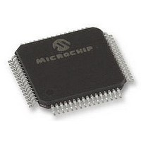
DSPIC30F5011-30I/PTG Microchip Technology, DSPIC30F5011-30I/PTG Datasheet - Page 213

DSPIC30F5011-30I/PTG
Manufacturer Part Number
DSPIC30F5011-30I/PTG
Description
16BIT MCU-DSP 30MHZ, SMD, 30F5011
Manufacturer
Microchip Technology
Series
DsPIC30Fr
Datasheet
1.DSPIC30F5011-30IPTG.pdf
(220 pages)
Specifications of DSPIC30F5011-30I/PTG
Core Frequency
30MHz
Embedded Interface Type
CAN, I2C, SPI, UART
No. Of I/o's
52
Flash Memory Size
66KB
Supply Voltage Range
2.5V To 5.5V
Operating Temperature Range
-40°C To
Lead Free Status / RoHS Status
Lead free / RoHS Compliant
External Interrupt Requests ................................................ 43
F
Fast Context Saving............................................................ 43
Flash Program Memory ...................................................... 45
I
I/O Pin Specifications
I/O Ports .............................................................................. 57
I
I
I
I
I
I
Idle Current (I
In-Circuit Serial Programming (ICSP) ......................... 45, 135
Input Capture (CAPX) Timing Characteristics .................. 186
Input Capture Module ......................................................... 77
Input Capture Operation During Sleep and Idle Modes ...... 78
Input Capture Timing Requirements ................................. 186
Input Change Notification Module ....................................... 61
2004 Microchip Technology Inc.
2
2
2
2
2
2
C 10-bit Slave Mode Operation ........................................ 91
C 7-bit Slave Mode Operation .......................................... 91
C Master Mode Operation ................................................ 93
C Master Mode Support ................................................... 93
C Module .......................................................................... 89
S Mode Operation .......................................................... 124
Input .......................................................................... 174
Output ....................................................................... 175
Parallel (PIO) .............................................................. 57
Reception.................................................................... 91
Transmission............................................................... 91
Reception.................................................................... 91
Transmission............................................................... 91
Baud Rate Generator.................................................. 94
Clock Arbitration.......................................................... 94
Multi-Master Communication, Bus Collision and
Reception.................................................................... 93
Transmission............................................................... 93
Addresses ................................................................... 91
Bus Data Timing Characteristics
Bus Data Timing Requirements
Bus Start/Stop Bits Timing Characteristics
General Call Address Support .................................... 93
Interrupts..................................................................... 92
IPMI Support ............................................................... 93
Operating Function Description .................................. 89
Operation During CPU Sleep and Idle Modes ............ 94
Pin Configuration ........................................................ 89
Programmer’s Model................................................... 89
Register Map............................................................... 95
Registers..................................................................... 89
Slope Control .............................................................. 93
Software Controlled Clock Stretching (STREN = 1).... 92
Various Modes ............................................................ 89
Data Justification....................................................... 124
Frame and Data Word Length Selection................... 124
Interrupts..................................................................... 78
Register Map............................................................... 79
CPU Idle Mode............................................................ 78
CPU Sleep Mode ........................................................ 78
dsPIC30F5011 Register Map (Bits 15-8) .................... 61
dsPIC30F5011 Register Map (Bits 7-0) ...................... 61
dsPIC30F5013 Register Map (Bits 15-8) .................... 61
Bus Arbitration .................................................... 94
Master Mode ..................................................... 196
Slave Mode ....................................................... 198
Master Mode ..................................................... 197
Slave Mode ....................................................... 199
Master Mode ..................................................... 196
Slave Mode ....................................................... 198
IDLE
) ............................................................ 170
Preliminary
Instruction Addressing Modes ............................................ 33
Instruction Set
Internal Clock Timing Examples ....................................... 180
Interrupt Controller
Interrupt Priority .................................................................. 40
Interrupt Sequence ............................................................. 43
Interrupts ............................................................................ 39
L
Load Conditions................................................................ 178
Low Voltage Detect (LVD) ................................................ 146
Low-Voltage Detect Characteristics.................................. 175
LVDL Characteristics ........................................................ 176
M
Memory Organization ......................................................... 21
Modes of Operation
Modulo Addressing ............................................................. 34
MPLAB ASM30 Assembler, Linker, Librarian ................... 160
MPLAB ICD 2 In-Circuit Debugger ................................... 161
MPLAB ICE 2000 High-Performance Universal
MPLAB ICE 4000 High-Performance Universal
MPLAB Integrated Development Environment Software.. 159
MPLINK Object Linker/MPLIB Object Librarian ................ 160
N
NVM
O
OC/PWM Module Timing Characteristics ......................... 187
Operating Current (I
Operating Frequency vs Voltage
Oscillator
dsPIC30F5011/5013
dsPIC30F5013 Register Map (Bits 7-0)...................... 61
File Register Instructions ............................................ 33
Fundamental Modes Supported ................................. 33
MAC Instructions ........................................................ 34
MCU Instructions ........................................................ 33
Move and Accumulator Instructions ........................... 34
Other Instructions ....................................................... 34
Overview................................................................... 154
Summary .................................................................. 151
Register Map .............................................................. 44
Traps .......................................................................... 41
Interrupt Stack Frame................................................. 43
Core Register Map ..................................................... 30
Disable...................................................................... 107
Initialization............................................................... 107
Listen All Messages.................................................. 107
Listen Only................................................................ 107
Loopback .................................................................. 107
Normal Operation ..................................................... 107
Applicability................................................................. 36
Incrementing Buffer Operation Example .................... 35
Start and End Address ............................................... 35
W Address Register Selection.................................... 35
Register Map .............................................................. 49
dsPIC30FXXXX-20 (Extended) ................................ 166
Configurations .......................................................... 138
In-Circuit Emulator................................................... 161
In-Circuit Emulator................................................... 161
Fail-Safe Clock Monitor .................................... 140
Fast RC (FRC).................................................. 139
Initial Clock Source Selection ........................... 138
Low Power RC (LPRC)..................................... 139
LP Oscillator Control......................................... 138
DD
) .................................................... 167
DS70116C-page 211


