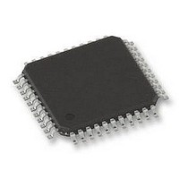
SAF-C505CA-LM Infineon Technologies, SAF-C505CA-LM Datasheet - Page 12

SAF-C505CA-LM
Manufacturer Part Number
SAF-C505CA-LM
Description
IC, 8BIT MCU ROM/ROMLESS, SMD
Manufacturer
Infineon Technologies
Datasheet
1.SAF-C505CA-LM.pdf
(88 pages)
Specifications of SAF-C505CA-LM
No. Of I/o's
34
Ram Memory Size
256Byte
Cpu Speed
20MHz
No. Of Timers
3
No. Of Pwm Channels
4
Digital Ic Case Style
MQFP
Supply Voltage
RoHS Compliant
Core Size
8bit
Oscillator Type
External, Internal
Controller Family/series
C500
Peripherals
ADC
Rohs Compliant
Yes
Available stocks
Company
Part Number
Manufacturer
Quantity
Price
Company:
Part Number:
SAF-C505CA-LM
Manufacturer:
INFINEON
Quantity:
5 510
Company:
Part Number:
SAF-C505CA-LM
Manufacturer:
BB
Quantity:
5 510
Part Number:
SAF-C505CA-LM
Manufacturer:
INFIENON
Quantity:
20 000
Company:
Part Number:
SAF-C505CA-LM CA
Manufacturer:
INFINEON
Quantity:
1 554
Company:
Part Number:
SAF-C505CA-LM CA
Manufacturer:
Infineon Technologies
Quantity:
10 000
Part Number:
SAF-C505CA-LM CA
Manufacturer:
INFINEON/英飞凌
Quantity:
20 000
Table 2
Pin Definitions and Functions (cont’d)
Symbol
P4.0
P4.1
XTAL2
XTAL1
*) I = Input
Data Sheet
O = Output
6
28
14
15
Pin Number
I/O
*)
I/O
I/O
O
I
Function
Port 4
is a 2-bit quasi-bidirectional port with internal pull-up
arrangement. Port 4 pins that have 1’s written to them are
pulled high by the internal pull-up transistors and in that
state can be used as inputs. As inputs, port 4 pins being
externally pulled low will source current (I
characteristics) because of the internal pullup transistors.
The output latch corresponding to the secondary function
RXDC must be programmed to a one (1) for that function to
operate. The secondary functions are assigned to the two
pins of port 4 as follows (C505C and C505CA only) :
P4.0 / TXDC
P4.1 / RXDC
XTAL2
Output of the inverting oscillator amplifier.
XTAL1
Input to the inverting oscillator amplifier and input to the
internal clock generator circuits.
To drive the device from an external clock source, XTAL1
should be driven, while XTAL2 is left unconnected. To
operate above a frequency of 16 MHz, a duty cycle of the
etxernal clock signal of 50 % should be maintained.
Minimum and maximum high and low times as well as rise/
fall times specified in the AC characteristics must be
observed.
8
Transmitter output of CAN controller
Receiver input of CAN controller
C505/C505C/C505A/C505CA
IL
, in the DC
12.00


