3RT10152BB41 SIEMENS, 3RT10152BB41 Datasheet - Page 8
3RT10152BB41
Manufacturer Part Number
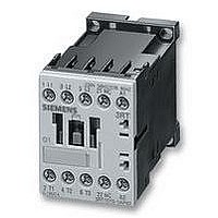
3RT10152BB41
Description
CONTACTOR, AC-3, 3KW/400V
Manufacturer
SIEMENS
Datasheet
1.3RT10161BB41.pdf
(70 pages)
Specifications of 3RT10152BB41
Operating Voltage
24VDC
Switching Power Ac3
3kW
Switching Current Ac1
18A
Switching Current Ac3
7A
No. Of Poles
3
Contacts
1NO
Relay Mounting
DIN Rail
Coil Voltage Vdc Nom
24V
Contact Configuration
1NO


■
3RT10 contactors, 3-pole, 3 ... 250 kW
Overview
3RT10 contactors, 3-pole, sizes S00 to S3, up to 45 kW
AC and DC operation
IEC 60947, EN 60947 (VDE 0660)
The 3RT1 contactors are climate-proof. They are finger-safe
according to EN 50274.
The 3RT1 contactors are available with screw terminals or with
Cage Clamp terminals.
Size S00 contactors have an auxiliary contact integrated in the
basic unit. The basic units of sizes S0 to S3 contain only the main
circuits.
All basic units can be extended with auxiliary switch blocks.
For size S0 and higher, complete units with 2 NO + 2 NC are
available (connection designation according to EN 50012). The
auxiliary switch block can be removed
LV 1 T).
In addition, complete units with permanently mounted auxiliary
switch block (2 NO + 2 NC according to EN 50012) are offered
for sizes S00 and S0. These versions are built according to
special Swiss regulations "SUVA" and are distinguished
externally by a red identification plate.
The size S3 contactors have removable box terminals for the
main conductor connections. This permits connection of ring
terminal lugs or busbars.
Contact reliability
If voltages ˆ 110 V and currents ˆ 100 mA are to be switched,
the auxiliary contacts of the 3RT1 contactor or 3RH11 contactor
relay should be used as they guarantee a high level of contact
reliability.
These auxiliary contacts are suitable for electronic circuits with
currents ˜ 1 mA at a voltage of 17 V.
Short circuit protection of the contactors
For more information about short circuit protection of contactors
without overload relay, see Technical Specifications. For more
informaiton about short circuit protection of the contactors with
overload relay, see "Overload Relays". When installing fuseless
motor feeders, the combinations of circuit-breakers and
contactors described under "Fuseless Load Feeders" must be
used.
Motor protection
3RU11 thermal overload relays or 3RB20 solid-state overload
relays can be fitted to the 3RT1 contactors for protection against
overload. The overload relays must be ordered separately.
Overvoltage damping
3RT1 contactors can be retrofitted with RC elements, varistors,
diodes or diode assemblies (assembly of diode and Zener diode
for short tripping times) for supressing opening surges in the
coil.
The surge suppressors are plugged onto the front of size S00
contactors. Space is provided for them next to a snap-on
auxiliary switch block.
For size S0 to S3 contactors, varistors and RC elements can be
snapped on either on the top or directly below the coil
connections. Diode assemblies are available in 2 different
versions on account of their polarity. Depending on the
application they can be connected either only at the bottom
(assembly with circuit-breaker) or only at the top (assembly with
overload relay).
3/8
3RT, 3TB, 3TF Contactors for Switching Motors
Siemens LV 1 · 2006
(for more information see
The plug-in direction of the diodes and diode assemblies is
specified by coding.
Exceptions:
3RT19 26-1T.00 and
3RT19 36-1T.00; the plug-in direction is indicated here with "+"
and "-".
Coupling relays are supplied either without overvoltage
damping or with a varistor or diode connected as standard,
according to the version.
Note:
The OFF-delay times of the NO contacts and the ON-delay times
of the NC contacts increase if the contactor coils are damped
against voltage peaks (noise suppression diode 6 to 10 times;
diode assemblies 2 to 6 times, varistor +2 to 5 ms).
3RT10 contactors, 3-pole, sizes S6 to S12,
> 45 to 250 kW
• 3RT10, contactors for switching motors,
• 3RT12, vacuum contactors for switching motors,
• 3RT14, contactors for AC-1 applications.
Operating mechanism types
Two types of solenoid operation are available:
• Conventional operating mechanism
• Solid-state operating mechanism (with 3 performance levels)
UC operation
The contactors can be operated with AC (40 to 60 Hz) as well as
with DC.
Withdrawable coils
For simple coil replacement, e.g. if the application is replaced,
the magnetic coil can be pulled out upwards after the release
mechanism has been actuated and can be replaced by any
other coil of the same size.
Auxiliary contact complement
The contactors can be fitted with up to 8 auxiliary contacts
(identical auxiliary switch blocks from S0 to S12). Of these, no
more than 4 are permitted to be NC contacts.
3RT10 and 3RT14 contactors:
Auxiliary contacts mounted laterally and on front
3RT12 vacuum contactors:
Auxiliary contacts mounted laterally
Contactors with conventional operating mechanism
Version 3RT1...-.A:
The magnetic coil is switched directly on and off with the control
supply voltage U
Multi-voltage range for the control supply voltage U
A single coil covers several control supply voltages of similar
ranges which are used worldwide, e.g. UC 110-115-120-127 V
or UC 220-230-240 V.
In addition, allowance is also made for a coil operating range of
0.8 times the lower (U
rated control supply voltage within which the contactor switches
reliably and no thermal overloading occurs.
s
by way of terminals A1/A2.
s min
) and 1.1 times the upper (U
s
:
s max
)
Related parts for 3RT10152BB41
Image
Part Number
Description
Manufacturer
Datasheet
Request
R

Part Number:
Description:
Intel 80C32 - Siemens SAB-C501, Nearest Equivalent Replacement
Manufacturer:
Siemens Semiconductor Group
Part Number:
Description:
IGBT MODULE
Manufacturer:
Siemens Semiconductor Group
Datasheet:
Part Number:
Description:
SIMOPAC Module (Power module Single switch N channel Enhancement mode)
Manufacturer:
Siemens Semiconductor Group
Datasheet:
Part Number:
Description:
(BSMxxx) TRANSISTOR
Manufacturer:
Siemens Semiconductor Group
Datasheet:
Part Number:
Description:
SIMOPAC Module (Power module Single switch N channel Enhancement mode)
Manufacturer:
Siemens Semiconductor Group
Datasheet:
Part Number:
Description:
main ratings
Manufacturer:
Siemens Semiconductor Group
Datasheet:
Part Number:
Description:
Manufacturer:
Siemens Semiconductor Group
Datasheet:
Part Number:
Description:
Manufacturer:
Siemens Semiconductor Group
Datasheet:
Part Number:
Description:
Manufacturer:
Siemens Semiconductor Group
Datasheet:
Part Number:
Description:
ICs for Consumer Electronics
Manufacturer:
Siemens Semiconductor Group
Datasheet:
Part Number:
Description:
Video and Sound IF with V & S SCART
Manufacturer:
Siemens Semiconductor Group
Datasheet:
Part Number:
Description:
Manufacturer:
Siemens Semiconductor Group
Datasheet:
Part Number:
Description:
Multistandard Sound IF
Manufacturer:
Siemens Semiconductor Group
Datasheet:
Part Number:
Description:
MULTISTANDARD AM FM SOUND IF IC
Manufacturer:
Siemens Semiconductor Group
Datasheet: