3RT10152BB41 SIEMENS, 3RT10152BB41 Datasheet - Page 9
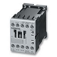
3RT10152BB41
Manufacturer Part Number
3RT10152BB41
Description
CONTACTOR, AC-3, 3KW/400V
Manufacturer
SIEMENS
Datasheet
1.3RT10161BB41.pdf
(70 pages)
Specifications of 3RT10152BB41
Operating Voltage
24VDC
Switching Power Ac3
3kW
Switching Current Ac1
18A
Switching Current Ac3
7A
No. Of Poles
3
Contacts
1NO
Relay Mounting
DIN Rail
Coil Voltage Vdc Nom
24V
Contact Configuration
1NO


Contactors with solid-state operating mechanism
The magnetic coil is supplied selectively with the power required
for reliable switching and holding by series-connected control
electronics.
• Wide voltage range for the control supply voltage U
• Extended operating range 0.7 to 1.25 x U
• Bridging temporary voltage dips:
• Defined ON and OFF thresholds:
• Low control power consumption when closing and in the
Electromagnetic compatibility (EMC)
The contactors with solid-state operating mechanism comply
with the requirements for operation in industrial installations.
• Interference immunity
• Emitted interference
Note:
When used with converters, the control cables must be routed
separately from the load cables of the converter.
Indication of remaining lifetime (RLT)
Main contactor contacts are working parts which must be
replaced in good time when the end of their service life has been
reached. The degree of contact erosion and thus the electrical
endurance (= number of operating cycles) depends on the
loading, utilization category, duty type, etc. Routine
checks/visual inspections by the service personnel are needed
in order to monitor the state of the main contacts. The "remaining
lifetime indication" function takes over this task. It does not count
the number of operating cycles – which does not provide
information about contact erosion – but instead electronically
identifies, evaluates and stores the actual progress of erosion of
each one of the three main contacts, and outputs a warning
when specified limits are reached. The stored data are not lost
even if the control supply voltage for A1/A2 fails. After
replacement of the main contacts, measurement the remaining
lifetime must be reset using the "RESET" button (hold down
RESET button for about 2 seconds using a pen or similar tool).
Compared with the conventional operating mechanism, the
solid-state operating mechanism covers an even broader
range of control supply voltages used worldwide within one
coil variant. For example, the coil for UC 200 to 277 V
(U
254-277 V used worldwide.
The wide range for the rated control supply voltage and the
additionally allowed coil operating range of 0.8 x U
1.1 x U
least 0.7 to 1.25 x U
reliably, for the most common control supply voltages of 24,
110 and 230 V.
Control voltage failures dipping to 0 V (at A1/A2) are bridged
for up to approx. 25 ms to avoid unintentional tripping.
For voltages of ˜ 0.8 x U
reliably switch the contactor ON, and as of ˆ 0.5 x U
reliably switched off. The differential travel in the switching
thresholds prevents the main contacts from chattering as well
as increased wear or welding when operated in weak,
unstable networks. This also prevents thermal overloading of
the contactor coil if the voltage applied is too low (contactor
does not close properly and is continuously operated with
overexcitation).
closed state.
- Burst (IEC 61000-4-4): 4 kV
- Surge (IEC 61000-4-5): 4 kV
- Electrostatic discharge, ESD (IEC 61000-4-2): 8/15 kV
- Electromagnetic field (IEC 61000-4-3): 10 V/m
- Limit value class A according to EN 55011
s min
s max
to U
s max
results in an extended coil operating range of at
) covers the voltages 200-208-220-230-240-
s
, within which the contactors will operate
s min
and higher the electronics will
3RT, 3TB, 3TF Contactors for Switching Motors
s
:
s min
s
s min
:
to
it is
Advantages:
• Signaling through relay contact or AS-i when remaining
• Additional visual indication of various levels of erosion by
• Early warning to replace contacts
• Optimum utilization of contact material
• Visual inspection of the condition of contacts no longer
• Reduction of ongoing operating costs
• Optimum planning of maintenance measures
• Avoidance of unforeseen plant downtimes
3RT1. ..-.N version: for 24 V DC PLC output
2 control options:
• Control without an interface directly through a
Note:
Set the slide switch for PLC operation to "PLC ON" before
commissioning (factory setting: "PLC OFF").
• Conventional control by applying the control supply voltage at
Note:
Slide switch must be in "PLC OFF" position
(= factory setting).
A1/A2 through a switching contact.
lifetime is 20 %, i.e. contact material wear is 80 %
means of LEDs on the laterally mounted solid-state module
when remaining lifetime is 60 % (green), 40 % (orange) and
20 % (red)
necessary
24 V DC/˜ 30 mA PLC output (EN 61131-2). Connection by
means of 2-pole plug-in connection. The screwless spring-
operated connector is part of the scope of supply. The control
supply voltage which supplies the solenoid operating
mechanism must be connected to A1/A2.
3RT10 contactors, 3-pole, 3 ... 250 kW
$ Slide switch must be in
$ Slide switch must be in
% Plug-in connection, 2-pole
"PLC ON" position
"PLC OFF" position
Siemens LV 1 · 2006
3/9
Related parts for 3RT10152BB41
Image
Part Number
Description
Manufacturer
Datasheet
Request
R

Part Number:
Description:
Intel 80C32 - Siemens SAB-C501, Nearest Equivalent Replacement
Manufacturer:
Siemens Semiconductor Group
Part Number:
Description:
IGBT MODULE
Manufacturer:
Siemens Semiconductor Group
Datasheet:
Part Number:
Description:
SIMOPAC Module (Power module Single switch N channel Enhancement mode)
Manufacturer:
Siemens Semiconductor Group
Datasheet:
Part Number:
Description:
(BSMxxx) TRANSISTOR
Manufacturer:
Siemens Semiconductor Group
Datasheet:
Part Number:
Description:
SIMOPAC Module (Power module Single switch N channel Enhancement mode)
Manufacturer:
Siemens Semiconductor Group
Datasheet:
Part Number:
Description:
main ratings
Manufacturer:
Siemens Semiconductor Group
Datasheet:
Part Number:
Description:
Manufacturer:
Siemens Semiconductor Group
Datasheet:
Part Number:
Description:
Manufacturer:
Siemens Semiconductor Group
Datasheet:
Part Number:
Description:
Manufacturer:
Siemens Semiconductor Group
Datasheet:
Part Number:
Description:
ICs for Consumer Electronics
Manufacturer:
Siemens Semiconductor Group
Datasheet:
Part Number:
Description:
Video and Sound IF with V & S SCART
Manufacturer:
Siemens Semiconductor Group
Datasheet:
Part Number:
Description:
Manufacturer:
Siemens Semiconductor Group
Datasheet:
Part Number:
Description:
Multistandard Sound IF
Manufacturer:
Siemens Semiconductor Group
Datasheet:
Part Number:
Description:
MULTISTANDARD AM FM SOUND IF IC
Manufacturer:
Siemens Semiconductor Group
Datasheet: