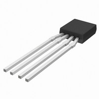
KMZ10C,112 NXP Semiconductors, KMZ10C,112 Datasheet - Page 40

KMZ10C,112
Manufacturer Part Number
KMZ10C,112
Description
IC MAGNETIC FIELD SENSOR SOT195
Manufacturer
NXP Semiconductors
Type
Special Purposer
Specifications of KMZ10C,112
Sensing Range
2mV/V
Voltage - Supply
5 V ~ 10 V
Output Type
Analog
Operating Temperature
-40°C ~ 150°C
Package / Case
SOT-195
Mounting Style
SMD/SMT
Maximum Operating Temperature
+ 150 C
Minimum Operating Temperature
- 40 C
Supply Voltage (min)
5 V
Supply Voltage (max)
10 V
Operating Temperature (min)
-40C
Operating Supply Voltage (typ)
5V
Lead Free Status / RoHS Status
Lead free / RoHS Compliant
Current - Supply
-
Current - Output (max)
-
Features
-
Lead Free Status / Rohs Status
Lead free / RoHS Compliant
Other names
933698480112
KMZ10C T/R
KMZ10C T/R
KMZ10C T/R
KMZ10C T/R
Philips Semiconductors
Both these first two set-ups allow current measurement
without breaking the conductor or interfering with the
circuit in any way, providing a distinct advantage over
resistor based systems. They can be used, for example,
for measuring the current in a headlamp-failure detection
system in motor vehicles or in clamp-on (non-contacting)
meters, as used in the power industry.
For applications where an analog signal is measured, such
as in these two measurement set-ups, a good evaluation
circuit should be used to allow for temperature drift
compensation and for offset and sensitivity adjustment.
This applies generally to measurement circuits using
magnetoresistive sensors. This is discussed in more detail
in Chapter “Weak field measurements”.
C
In any measurement set-up, there are always other
magnetic fields present besides that generated by the
current, such as the earth’s magnetic field, and these
interfere with the measurement. A more accurate
measurement set-up uses two magnetic field sensors, to
compensate for these external fields (see Fig.46).
The first sensor detects both the interference field and the
current-field in the positive direction, and the second
sensor detects the interference field in the negative
direction and the current-field in the positive direction.
These two signals are added, cancelling out the
interference field, leaving a signal that is representative of
only the current-field.
This set-up works with homogeneous interference fields
like that from the earth. Inhomogeneous fields, which will
produce different interference fields inside the two
sensors, will still affect the current measurement. This
error can be minimized by keeping the distance between
the sensors small or integrating both sensors onto a single
piece of silicon. Large magnetic fields which fall outside
the range of the sensors can also produce errors, so the
size of external fields must be limited.
1998 Jun 12
OMPENSATING FOR EXTERNAL MAGNETIC FIELDS
Magnetic field sensors
40
Another advantage of using two sensors, at a fixed
distance apart, is that measurement is less sensitive to
sensor-conductor distance. If the conductor is moved
closer to the first sensor, then its distance from the second
sensor is correspondingly increased and the effect is
compensated. For small differences in distance between
the conductor and sensors, sensitivity is nearly constant
and the conductor need not be fixed in place. This method
lends itself to measurement of current in free cables.
Table 8 summarizes the various advantages and
disadvantages of one-sensor and two-sensor
measurement set-ups as described above.
handbook, halfpage
Fig.46 Diagram showing two sensors to measure
current.
H disturb
sensor 1
sensor 2
MGG426
General


