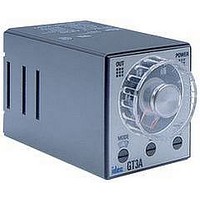
GT3F-2AD24 IDEC, GT3F-2AD24 Datasheet - Page 19

GT3F-2AD24
Manufacturer Part Number
GT3F-2AD24
Description
Electromechanical General Purpose Timer
Manufacturer
IDEC
Type
Off Delayr
Datasheet
1.GT3A-4AD24.pdf
(41 pages)
Specifications of GT3F-2AD24
Leaded Process Compatible
No
No. Of Pins
8
Peak Reflow Compatible (260 C)
No
Switch Function
DPDT
Supply Voltage
250VAC
Time Range Min
0.05s
Supply Current
5A
Time Range Max
600s
Rohs Compliant
No
Lead Free Status / RoHS Status
Contains lead / RoHS non-compliant
G
GT3D Series
G-32
Time Remaining
Time Elapsed
Time Remaining
Time Elapsed
Time Remaining
Time Elapsed
ON-Delay One-Shot 1
Cycle One-Shot
ON-Delay One-Shot 2
1
1
2
2
3
3
www.idec.com
(Contact Input)
ResetStartGate
Item
Power
Delayed
Contact
Indicator
Digital
Time
Display
Set Time
Item
Power
Delayed
Contact
Indicator
Digital
Time
Display
Set Time
Item
Power
Delayed
Contact
Indicator
Digital
Time
Display
Set Time
Start
Reset
Gate
Start
Reset
Gate
Start
Reset
Gate
(-)
ON or L
ON or L
ON or L
ON or L
ON or L
ON or L
ON or L
ON or L
ON or L
(NC)
3
(NC)
(NC)
Terminal No.
2-10 (POWER)
(NO)
OUT
DOWN
UP
Terminal No.
2-10 (POWER)
(NO)
OUT
DOWN
UP
Terminal No.
2-10 (POWER)
(NO)
OUT
DOWN
UP
4
2
5
POWER
1
1-4
8-11
1-3
9-11
1-4
8-11
1-3
9-11
1-4
8-11
1-3
9-11
2-6
2-7
2-6
2-6
6
2-7
2-7
2-5
2-5
2-5
11
7
10
8
9
GT3D-8 Timing Diagrams
(+)
T
T
T
Delayed DPDT
USA: (800) 262-IDEC or (408) 747-0550, Canada: (888) 317-IDEC
To
Reset Start Gate
To
To
T
(Transistor Input)
To
Ta
T
Ta
To
Ta
T
(-)
T
Tb
3
4
2
Tb
Operation
T
5
Operation
Operation
POWER
1
Ta
Tb
6
T’
11
7
10
T
8
9
(+)
T
Tb
T’’ To
To
T’
Timers
Note: T = Set time
T’
Ta = Shorter than set time
Tb = Shorter than single-shot
T = T’ + T”
T0 = Single-shot output time
T’’
To
T
Ta
output time
(selected from
A, B, C, D, E or F)
Tb
T’’
Tb


