GT3F-2AD24 IDEC, GT3F-2AD24 Datasheet - Page 41
GT3F-2AD24
Manufacturer Part Number
GT3F-2AD24
Description
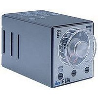
Electromechanical General Purpose Timer
Manufacturer
IDEC
Type
Off Delayr
Datasheet
1.GT3A-4AD24.pdf
(41 pages)
Specifications of GT3F-2AD24
Leaded Process Compatible
No
No. Of Pins
8
Peak Reflow Compatible (260 C)
No
Switch Function
DPDT
Supply Voltage
250VAC
Time Range Min
0.05s
Supply Current
5A
Time Range Max
600s
Rohs Compliant
No
Lead Free Status / RoHS Status
Contains lead / RoHS non-compliant


G
Load Current
With inductive, capacitive, and incandescent lamp loads, inrush current more
than 10 times the rated current may cause welded contacts and other undes-
ired effects. The inrush current and steady-state current must be taken into
consideration when specifying a timer.
Contact Protection
Switching an inductive load generates a counter-electromotive force (back
EMF) in the coil. The back EMF will cause arcing, which may shorten the con-
tact life and cause imperfect contact. Application of a protection circuit is
recommended to safeguard the contacts.
Temperature and Humidity
Use the timer within the operating temperature and operating humidity
ranges and prevent freezing or condensation. After the timer has been stored
below its operating temperature, leave the timer at room temperature for a
sufficient period of time to allow it to return to operating temperatures before
use.
Environment
Avoid contact between the timer and sulfurous or ammonia gases, organic
solvents (alcohol, benzine, thinner, etc.), strong alkaline substances, or strong
acids. Do not use the timer in an environment where such substances are
prevalent. Do not allow water to run or splash on the timer.
Vibration and Shock
Excessive vibration or shocks can cause the output contacts to bounce, the timer
should be used only within the operating extremes for vibration and shock resis-
tance. In applications with significant vibration or shock, use of hold down
springs or clips is recommended to secure a timer to its socket.
General Instructions
Timing accuracies are calculated from the following formulas:
Repeat Error
Voltage Error
T
T
Temperature Error
T
T
Setting Error
G-68
r:
v
t
20
: Average of measured values at °C
: Average of measured values at voltage V
Average of measured values at the rated voltage
: Average of measured values at 20°C
= ± 1 x Maximum Measured Value – Minimum Measured Value x 100%
= ± Tv - Tr x 100%
= ± Tt - T20 x 100%
= ± Average of Measured Values - Set Value x 100%
www.idec.com
Tr
T20
2
Maximum Scale Value
General Instructions for All Timer Series
Maximum Scale Value
Timing Accuracy Formulas
USA: (800) 262-IDEC or (408) 747-0550, Canada: (888) 317-IDEC
Time Setting
The time range is calibrated at its maximum time scale; so it is desirable to
use the timer at a setting as close to its maximum time scale as possible. For
a more accurate time delay, adjust the control knob by measuring the operat-
ing time with a watch before application.
Input Contacts
Use mechanical contact switch or relay to supply power to the timer. When
driving the timer with a solid-state output device (such as a two-wire proxim-
ity switch, photoelectric switch, or solid-state relay), malfunction may be
caused by leakage current from the solid-state device. Since AC types com-
prise a capacitive load, the SSR dielectric strength should be two or more
times the power voltage when switching the timer power using an SSR.
Generally, it is desirable to use mechanical contacts whenever possible to
apply power to a timer or its signal inputs. When using solid state devices, be
cautious of inrushes and back-EMF that may exceed the ratings on such
devices. Some timers are specially designed so that signal inputs switch at a
lower voltage than is used to power the timer (models designated as “B"
type).
Timers
Related parts for GT3F-2AD24
Image
Part Number
Description
Manufacturer
Datasheet
Request
R

Part Number:
Description:
GT3F-1AD24 8PIN DPDT TRUE POWER OFF DELAY TIMER
Manufacturer:
IDEC
Datasheet:
Part Number:
Description:
GT3F-1EAF20 11 PIN SPDT TRUE POWER OFF DELAY TIMER
Manufacturer:
IDEC
Datasheet:
Part Number:
Description:
GT3F-2EAF20 11 PIN DPDT TRUE POWER OFF DELAY TIMER
Manufacturer:
IDEC
Datasheet:
Part Number:
Description:
Relay; E-Mech; Timing; Off Delay; DPDT; Cur-Rtg 3A; Ctrl-V 100-240AC; Socket Mnt; Screw
Manufacturer:
IDEC Corporation
Datasheet:
Part Number:
Description:
Cable; Between IDEC MicroSmart (port 1 or 2) and HG2F/3F/4F; 5 ft.
Manufacturer:
IDEC Corporation
Datasheet:
Part Number:
Description:
Cable; Between IDEC Micro^3C/ONC/MicroSmart (port 2) PLCs and HG2F/3F/4F; 5 ft.
Manufacturer:
IDEC Corporation
Datasheet:
Part Number:
Description:
Angled Key for Idec HS6B Safety Switch
Manufacturer:
IDEC Corporation
Datasheet:
Part Number:
Description:
Accessory, L-Shaped Key for Idec HS5B and HS5E Safety Switch
Manufacturer:
IDEC Corporation
Datasheet:
Part Number:
Description:
Accessory, Straight Key for Idec HS5B and HS5E Safety Switch
Manufacturer:
IDEC Corporation
Datasheet:
Part Number:
Description:
Straight Key for Idec HS6B Safety Switch
Manufacturer:
IDEC Corporation
Datasheet:
Part Number:
Description:
Antenna/ Sensor/ and Communications Trunk Line Connections
Manufacturer:
Hirose Electric
Datasheet:
Part Number:
Description:
Interface Portions and In-line Portions of the Various Units and Devices
Manufacturer:
Hirose Electric
Datasheet:
Part Number:
Description:
Antenna, Sensor, and Communications Trunk Line Connections
Manufacturer:
HIROSE [Hirose Electric]
Datasheet:
Part Number:
Description:
INDICATOR INCANDESCENT LAMP, GREEN
Manufacturer:
IDEC
Datasheet:

Part Number:
Description:
LAMP, INDICATOR, INCAND, AMB
Manufacturer:
IDEC
Datasheet: