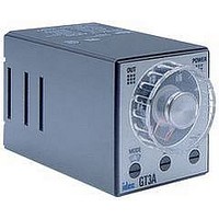
GT3F-2AD24 IDEC, GT3F-2AD24 Datasheet - Page 20

GT3F-2AD24
Manufacturer Part Number
GT3F-2AD24
Description
Electromechanical General Purpose Timer
Manufacturer
IDEC
Type
Off Delayr
Datasheet
1.GT3A-4AD24.pdf
(41 pages)
Specifications of GT3F-2AD24
Leaded Process Compatible
No
No. Of Pins
8
Peak Reflow Compatible (260 C)
No
Switch Function
DPDT
Supply Voltage
250VAC
Time Range Min
0.05s
Supply Current
5A
Time Range Max
600s
Rohs Compliant
No
Lead Free Status / RoHS Status
Contains lead / RoHS non-compliant
www.idec.com
Select the desired
time display and
operation modes.
Select a time range that
contains the desired
period of time.
Set the precise period of time desired by using the
It is important to remember that the
tion of the Digital Time Display. Changing the
minutes, hours) as well as the decimal point location.
Step 1
Step 2
Step 3
Timers
remaining
remaining
remaining
remaining
Display
elapsed
elapsed
elapsed
elapsed
0.01 seconds to 9.99 seconds
0.1 seconds to 99.9 seconds
1 second to 999 seconds
0.1 minutes to 99.9 minutes
1 minute to 999 minutes
0.1 hours to 99.9 hours
Mode
Time
Time
Time
Time
Time
Time
Time
Time
Time
Timed OUT Indicator
Digital Time Display
(LCD backlit
with red LED)
Base Time Ranges
Desired Operation
Desired Operation
Selector
1
Indication Mode
USA: (800) 262-IDEC or (408) 747-0550, Canada: (888) 317-IDEC
Indicator Mode
1
1
1
1
1
1
1
1
1
1
1
1
Time Range Selector not only selects the time range but also influences the interpreta-
Selector
Instructions: Setting GT3D-2, GT3D-3 Timers
1
Desired Mode/Selection
Time Range Selector setting changes the units of time measurement (seconds,
Time Setting Digital Switch.
9.99
99.9
999
99.9
999
99.9
ON-delay 1
Interval
Cycle 1
Cycle 3
Decimal Point
Operation
Indicator
Mode
A, B, C, D
Selection
Selection
Time Range
Selector
Operation Mode Selector
A
B
C
D
Time Increment
Mode Selector
Indicator
M
M
S
S
H
H
Operation
A
D
B
C
Digital Switch
Time Setting
9.99S – 99.9H
Time Range Selector
1. Use the flat screwdriver to set the selectors.
Since selectors do not turn all the way around,
both clockwise and counterclockwise rotation
may be necessary.
2. The
whether the Digital Time Display shows the
time elapsed or time remaining. The
tion Mode Selector determines the desired
operation mode. Decide which display and
mode is desired, then use these two selec-
tors
3. The
blank modes which are not intended for use.
Always have this selector set to A, B, C, or D.
1. The
the decimal point indicator (9.99, 99.9, 999) and
the time increment indicators S (seconds), M
(minutes), and H (hours).
2. Chose which base time range contains the
targeted timer setting. Then use the
Range Selector to set the decimal point indica-
tor and time increment indicator to its corre-
sponding pair of settings.
3. Since these configurations offer a complete
range of settings from 0.01 seconds to 99.9
hours, the setting of 9.99 for minutes and the
9.99 and 999 settings for hours are not listed
and should not be used.
Use the
the desired period of time. It is important to
remember that the setting of the
Range Selector determines the units of time
measurement as well as the implied decimal
point location.
Indicator Mode Selector determines
to set the operation mode.
Operation Mode Selector has two
Time Range Selector controls both
Time Setting Digital Switch to set
Remarks
Remarks
Remarks
GT3D Series
Time
Time
Opera-
G-33
G


