PAXCK000 Red Lion Controls, PAXCK000 Datasheet - Page 11
PAXCK000
Manufacturer Part Number
PAXCK000
Description
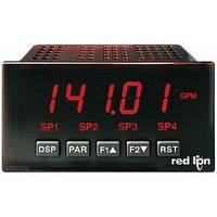
Digital Multifunction Timer
Manufacturer
Red Lion Controls
Type
Clock/Timerr
Datasheet
1.PAXTM000.pdf
(28 pages)
Specifications of PAXCK000
Time Range
0.001sec To 1hr
Power Consumption
18VA
Supply Voltage Ac, Min
85V
Signal Input Type
Pulse
Supply Voltage Max
250VAC
Time Range Max
999999h
Character Size
0.56"
Accuracy
±0.01% %
Connection Type
Cage-Clamp
Cut Out, Panel
3.62×1.77 "
Digit Height
0.56
Dimensions
4.2"L×3.8"W×1.95"H
Display Digit Height
0.56 "
Display Resolution
0.001 Sec. (Minimum Digit), 1 hr. (Single Digit)
Display Type
LED
Function
Real Time Clock/Timer
Humidity
0 to 85% (Max.) RH
Isolation Voltage
2300 V (RMS)
Length, Stripping
0.3 in. Wire
Memory Type
Non-Volatile EEPROM
Number Of Digits
6
Power, Rating
18 VA
Primary Type
Electronic
Range, Measurement
0 to 999999
Special Features
Programmable Function Keys
Standards
cULus Listed, CSA Certified
Temperature, Operating
0 to +50 °C
Termination
Cage Clamp
Torque
4.5 in.-lbs
Voltage, Range
85 to 250 VAC
Voltage, Supply
85 to 250 VAC
Four Separate Displays
Timer, Counter, Real-Time Clock and Date
Display Font Color
Red
No. Of Digits / Alpha
6
Supply Voltage Ac, Max
250V
Rohs Compliant
NA
Lead Free Status / RoHS Status
na


SECONDS
MINUTES
HOURS
Display Mode, the TMR annunciator indicates the Timer display is currently
being shown. An EXCHANGE PARAMETER LISTS feature, which includes
the Timer Start and Timer Stop Values, is explained in Module 2.
“Run/Stop” status of the Timer. The timing diagrams below reflect a Sinking
input setup (active low). A Sourcing input setup (active high) is available
through plug jumper selection (see Section 2.0). In this case, the logic levels of
the timing diagrams would be inverted.
type of Stop condition is cleared when a Timer Reset occurs, or another start
edge is applied.
Inhibit function. This function is also available through a User Input (see
Module 2). Timing diagrams are shown below for “
modes. The “
timer display value is also reset at “Time Start” edges. In the “
“
a Timer Start (Input A) or Timer Stop (Input B) edge occurs.
SELECTION
6.1 MODULE 1 - T
Level Active (Gated) Operation
INPUT A
INPUT B - Timer Inhibit (Level Active)
RANGE
* - Timer is reset at Time Start edge.
Module 1 is the programming module for the Timer Input Parameters. In the
This parameter determines how the Timer Input Signals affect the
The Timer can also be stopped using a Timer Stop Value or a Setpoint. This
For
” modes, the timer display value remains held and only updates when
,
Time
Start
MAXIMUM
DISPLAY
and
Time
Stop
Time
Start
TIMER INPUT OPERATION
” through “
RESOLUTION
*
DISPLAY
0.001 SEC
0.001 MIN
0.01 SEC
0.001 HR
0.01 MIN
operation, Input B provides a level active Timer
0.1 SEC
0.01 HR
0.1 MIN
23 TIMER RANGE SELECTIONS
(
Time
Stop
TIMER RANGE
0.1 HR
1 SEC
1 MIN
1 HR
= SEC;
= MIN;
MINUTES/SECONDS
HOURS/MINUTES
HOURS/MINUTES/SECONDS
DAYS/HOURS/MINUTES
” modes are identical except the
SELECTION
Edge Triggered Operation -1 Input
INPUT A
INPUT B - Timer Inhibit (Level Active)
RANGE
= HR;
IMER
,
Time
Start
MAXIMUM
DISPLAY
= DAY
” through “
Time
Stop
)
I
Time
Start
RESOLUTION
PARAMETER MENU
0.001 SEC
0.001 MIN
*
NPUT
DISPLAY
0.01 SEC
0.01 MIN
0.1 SEC
0.1 SEC
0.1 MIN
1 SEC
1 SEC
1 MIN
1 MIN
” and
Time
Stop
”
11
P
ARAMETERS
using relays or switch contacts as a signal source.
entered in the same display format as the Timer Range selected. Non-zero
values are normally used for “timing down” applications, but they can also
provide an “offset” value when timing up.
the Timer Inputs. Selecting
Value can be set or changed. The Stop Value is entered in the same display
format as the Timer Range selected. This Stop condition is cleared when a
Timer Reset occurs. Select
* - Timer is reset at Time Start edge.
Provides a 50 msec debounce for the Timer Inputs (A and B). Select
Timing direction can be reversed through a User Input. (See Module 2.)
The Timer returns to this value whenever a Timer Reset occurs. The value is
The Timer stops when this value is reached, regardless of the signal levels on
Edge Triggered Operation - 2 Input
INPUT A
INPUT B
Time
Start
,
Time
Stop
Time
Start
TIMER INPUT FILTERING
TIMER START VALUE
Time
Stop
TIMER STOP VALUE
TIMING DIRECTION
(
*
if a Stop Value is not being used.
will display the
to
to
)
Edge Triggered Operation - 2 Input,
with Display Hold
INPUT A
INPUT B
Display Update
Time Start,
sub-menu where the Stop
,
Display Update
Time Stop,
Display Update
Time Start,
*
Display
Update
when
Related parts for PAXCK000
Image
Part Number
Description
Manufacturer
Datasheet
Request
R

Part Number:
Description:
Counter
Manufacturer:
Red Lion Controls
Datasheet:
Part Number:
Description:
Miniature Length Sensor
Manufacturer:
Red Lion Controls
Datasheet:
Part Number:
Description:
Model Lsc - Single Channel Output Length Sensor
Manufacturer:
Red Lion Controls
Datasheet: