PAXCK000 Red Lion Controls, PAXCK000 Datasheet - Page 17
PAXCK000
Manufacturer Part Number
PAXCK000
Description
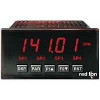
Digital Multifunction Timer
Manufacturer
Red Lion Controls
Type
Clock/Timerr
Datasheet
1.PAXTM000.pdf
(28 pages)
Specifications of PAXCK000
Time Range
0.001sec To 1hr
Power Consumption
18VA
Supply Voltage Ac, Min
85V
Signal Input Type
Pulse
Supply Voltage Max
250VAC
Time Range Max
999999h
Character Size
0.56"
Accuracy
±0.01% %
Connection Type
Cage-Clamp
Cut Out, Panel
3.62×1.77 "
Digit Height
0.56
Dimensions
4.2"L×3.8"W×1.95"H
Display Digit Height
0.56 "
Display Resolution
0.001 Sec. (Minimum Digit), 1 hr. (Single Digit)
Display Type
LED
Function
Real Time Clock/Timer
Humidity
0 to 85% (Max.) RH
Isolation Voltage
2300 V (RMS)
Length, Stripping
0.3 in. Wire
Memory Type
Non-Volatile EEPROM
Number Of Digits
6
Power, Rating
18 VA
Primary Type
Electronic
Range, Measurement
0 to 999999
Special Features
Programmable Function Keys
Standards
cULus Listed, CSA Certified
Temperature, Operating
0 to +50 °C
Termination
Cage Clamp
Torque
4.5 in.-lbs
Voltage, Range
85 to 250 VAC
Voltage, Supply
85 to 250 VAC
Four Separate Displays
Timer, Counter, Real-Time Clock and Date
Display Font Color
Red
No. Of Digits / Alpha
6
Supply Voltage Ac, Max
250V
Rohs Compliant
NA
Lead Free Status / RoHS Status
na


NOTE: Input A is shown as a Sourcing input (active high). If a Sinking input (active low) is used, the logic levels for Input A would be inverted.
* Refer to timing diagrams. These parameters are the actual Setpoint On/Off or Time-Out values set by the user for the specific application.
MODULE 6 - Setpoint Parameters (
MODULE 1 - Timer Input Parameters (
MODULE 2 - User Input Parameters (
DISPLAY
DISPLAY
INP OP
USEr-1
rSt
SPSEL
ASN-1
ACt-1
OUt-1
ON-1
SP-1
OFf-1
SPOf-1
tOUt-1
tstP-1
AUtO-1
OrSd-1
Lit-1
P-UP-1
DISPLAY
Parameter Settings for Predefined Timer Operating Modes
Timing Diagrams for Predefined Timer Operating Modes
On-Delay Timing
Off-Delay Timing
The input signal must be wired to both the Input A and
User Input 1 terminals. The Timer Input plug jumper and
the User Input plug jumper must both be set to the
same position (either both SNK or both SRC).
Repeat Cycle Timing
Output 1
Output 1
Output 1
Input A
Input A
Input A
PARAMETER
User Input 1
Reset Key
PARAMETER
Setpoint Select
Setpoint Assignment
Setpoint Action
Output Logic
Setpoint On
Setpoint On Value
Setpoint Off
Setpoint Off Value
Time-out Value
Timer Stop
Timer/Counter Auto Reset
Output Reset w/display Reset
Setpoint Annunciator
Power-up State
PARAMETER
Timer Input Operation
T1
T
T
T2
T1
EdrS-2
ON-dLY
ON-dLY
t-dSP
LAtCH
VALUE
ON-dLY
T
SP-1
T
NOr
NOr
OFF
N/A
N/A
N/A
N/A
NO
NO
NO
NO
T*
T
)
)
)
ON-OFF
t-Strt
EdrS-2
OF-dLY
rSt-L
OF-dLY
t-dSP
VALUE
0-OFF
OF-dLY
SP-1
NOr
NOr
OFF
N/A
N/A
NO
NO
NO
T*
17
ON-OFF
EdrS-2
rEPEAt
rEPEAt
t-dSP
VALUE
VALUE
0-OFF
rEPEAt
SP-1
NOr
NOr
OFF
N/A
N/A
NO
T1*
T2*
NO
NO
On-Delay / Interval Timing
Interval Timing (Level triggered)
The input signal must be wired to both the Input A and
User Input 1 terminals. The Timer Input plug jumper and
the User Input plug jumper must be set to opposite
positions (one SNK, one SRC) and the Input signal must
be a current sinking type (i.e. pulls input to common).
Interval Timing (Edge triggered)
Output 1
Output 1
Output 1
Input A
Input A
Input A
EdrS-2
dLYINt
dLYINt
t-dSP
t-OUt
VALUE
0-OFF
dLYINt
SP-1
NOr
NOr
OFF
N/A
T1*
N/A
N/A
T2*
NO
NO
NO
T
T
(
T1
SP1-YES
OrSt-E
ON-OFF
t-Strt
LEVrSt
t-dSP
VALUE
0-OFF
INt-L
INt-L
SP-1
INt-L
NOr
NOr
OFF
NO
N/A
N/A
NO
NO
T*
)
T2
T
t-Strt
EdrS-2
t-dSP
t-OUt
0-OFF
INt-E
INt-E
SP-1
INt-E
NOr
NOr
OFF
N/A
N/A
N/A
N/A
NO
NO
NO
T*
T
T
Related parts for PAXCK000
Image
Part Number
Description
Manufacturer
Datasheet
Request
R

Part Number:
Description:
Counter
Manufacturer:
Red Lion Controls
Datasheet:
Part Number:
Description:
Miniature Length Sensor
Manufacturer:
Red Lion Controls
Datasheet:
Part Number:
Description:
Model Lsc - Single Channel Output Length Sensor
Manufacturer:
Red Lion Controls
Datasheet: