EA-EDU-010 Embedded Artists, EA-EDU-010 Datasheet - Page 38
EA-EDU-010
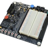
Manufacturer Part Number
EA-EDU-010
Description
MCU, MPU & DSP Development Tools LPC2138 EDUCATION BRD
Manufacturer
Embedded Artists
Specifications of EA-EDU-010
Processor To Be Evaluated
LPC2138
Data Bus Width
16 bit, 32 bit
Interface Type
I2C, SPI, UART
Core
ARM7TDMI-S
Dimensions
127 mm x 120 mm
Maximum Operating Temperature
+ 85 C
Operating Supply Voltage
3.3 V
Lead Free Status / RoHS Status
Lead free / RoHS Compliant


NXP Semiconductors
LPC2131_32_34_36_38
Product data sheet
12.2 RTC 32 kHz oscillator component selection
12.3 XTAL and RTCX Printed Circuit Board (PCB) layout guidelines
The RTC external oscillator circuit is shown in
integrated on chip, only a crystal, the capacitances C
externally to the microcontroller.
Table 12
capacitance of the crystal and is usually specified by the crystal manufacturer. The actual
C
different load capacitance, the circuit will oscillate at a slightly different frequency
(depending on the quality of the crystal) compared to the specified one. Therefore for an
accurate time reference it is advised to use the load capacitors as specified in
that belong to a specific C
this table are calculated from the internal parasitic capacitances and the C
from PCB and package are not taken into account.
Table 12.
The crystal should be connected on the PCB as close as possible to the oscillator input
and output pins of the chip. Take care that the load capacitors C
third overtone crystal usage have a common ground plane. The external components
must also be connected to the ground plain. Loops must be made as small as possible in
order to keep the noise coupled in via the PCB as small as possible. Also parasitics
should stay as small as possible. Values of C
accordingly to the increase in parasitics of the PCB layout.
Crystal load capacitance
C
11 pF
13 pF
15 pF
Fig 15. RTC oscillator modes and models: oscillation mode of operation and external
L
L
influences oscillation frequency. When using a crystal that is manufactured for a
gives the crystal parameters that should be used. C
crystal model used for C
Recommended values for the RTC external 32 kHz oscillator C
All information provided in this document is subject to legal disclaimers.
RTCX1
C X1
LPC2xxx
32 kHz XTAL
Rev. 5 — 2 February 2011
L
Maximum crystal series
resistance R
< 100 kΩ
< 100 kΩ
< 100 kΩ
. The value of external capacitances C
RTCX2
C X2
X1
/C
X2
S
evaluation
x1
LPC2131/32/34/36/38
Figure
and C
Single-chip 16/32-bit microcontrollers
X1
=
15. Since the feedback resistance is
x2
External load capacitors C
18 pF, 18 pF
22 pF, 22 pF
27 pF, 27 pF
and C
should be chosen smaller
L
X2
is the typical load
x1
need to be connected
, C
L
C L
R S
X1
x2
and C
002aaf495
, and C
© NXP B.V. 2011. All rights reserved.
X1
C P
/C
L
X2
. Parasitics
X2
specified in
x3
components
Table 12
in case of
X1
/C
38 of 45
X2
Related parts for EA-EDU-010
Image
Part Number
Description
Manufacturer
Datasheet
Request
R

Part Number:
Description:
MCU, MPU & DSP Development Tools LPC2148 EDUCATION BRD
Manufacturer:
Embedded Artists
Datasheet:

Part Number:
Description:
MCU, MPU & DSP Development Tools LPC2103 EDUCATION BRD
Manufacturer:
Embedded Artists
Datasheet:

Part Number:
Description:
MCU, MPU & DSP Development Tools EXPERIMENT EXPANSION BRD
Manufacturer:
Embedded Artists
Datasheet:

Part Number:
Description:
HEATSINK FOR TO-220 BLACK
Manufacturer:
Ohmite
Datasheet:

Part Number:
Description:
HEATSINK FOR TO-220 BLACK
Manufacturer:
Ohmite
Datasheet:

Part Number:
Description:
HEATSINK FOR TO-220 BLACK
Manufacturer:
Ohmite
Datasheet:

Part Number:
Description:
LCD Graphic Display Modules & Accessories Pure Green Backlight For DOG-M Series
Manufacturer:
ELECTRONIC ASSEMBLY
Datasheet:

Part Number:
Description:
LCD Graphic Display Modules & Accessories Grn LED Backlight For DOG-XL Series
Manufacturer:
ELECTRONIC ASSEMBLY
Datasheet:
Part Number:
Description:
LCD Graphic Display Modules & Accessories Green LED Backlight For DOG-L Series
Manufacturer:
ELECTRONIC ASSEMBLY
Datasheet:

Part Number:
Description:
KIT LPC3141 SODIMM 66X48 200POS
Manufacturer:
Embedded Artists
Datasheet:
Part Number:
Description:
KIT LPC3152 SODIMM 66X48 200POS
Manufacturer:
Embedded Artists
Datasheet:
Part Number:
Description:
BOARD OEM W/LPC2478 MCU
Manufacturer:
Embedded Artists
Datasheet:
Part Number:
Description:
KIT LPC3250 259 WITH QVGA
Manufacturer:
Embedded Artists
Datasheet: