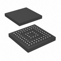
AD9393BBCZ-80 Analog Devices Inc, AD9393BBCZ-80 Datasheet - Page 24

AD9393BBCZ-80
Manufacturer Part Number
AD9393BBCZ-80
Description
Pb-free Low Power HDMI Rx
Manufacturer
Analog Devices Inc
Datasheet
1.AD9393BBCZ-80.pdf
(40 pages)
Specifications of AD9393BBCZ-80
Applications
Video
Interface
HDMI
Voltage - Supply
3.15 V ~ 3.47 V
Package / Case
76-CSPBGA
Mounting Type
Surface Mount
Lead Free Status / RoHS Status
Lead free / RoHS Compliant
Available stocks
Company
Part Number
Manufacturer
Quantity
Price
Company:
Part Number:
AD9393BBCZ-80
Manufacturer:
Analog Devices Inc
Quantity:
135
Company:
Part Number:
AD9393BBCZ-80
Manufacturer:
FUJ
Quantity:
1 445
Company:
Part Number:
AD9393BBCZ-80
Manufacturer:
Analog Devices Inc
Quantity:
10 000
Part Number:
AD9393BBCZ-80
Manufacturer:
ADI/亚德诺
Quantity:
20 000
AD9393
BT656 GENERATION
0x27—Bit[4], BT656 EN
This bit enables the output to be BT656-compatible with the
defined start of active video (SAV) and the end of active video
(EAV) controls to be inserted. These require specification of the
number of active lines, active pixels per line, and delays to place
these markers. 0 = disable BT656 video mode. 1 = enable BT656
video mode. The power-up default setting is 0.
0x27—Bit[3], Force DE Generation
This bit allows the use of the internal DE generator in DVI
mode. 0 = internal DE generation disabled. 1 = force DE
generation via programmed registers. The power-up default
setting is 0.
0x27—Bits[2:0], Interlace Offset
These bits define the offset in HSYNCs from Field 0 to Field 1.
The power-up default setting is 000.
0x28—Bits[7:2], VSYNC Delay
These bits set the delay (in lines) from the leading edge of
VSYNC to active video. The power-up default setting is 24d.
0x28—Bits[1:0], HSYNC Delay MSB and 0x29—Bits[7:0],
HSYNC Delay LSB
These 10 bits set the delay (in pixels) from the HSYNC leading
edge to the start of active video. The power-up default setting is
0x104.
0x2A—Bits[3:0], Line Width MSB and 0x2B—Bits[7:0]
Line Width LSB
These 12 bits set the width of the active video line (in pixels).
The power-up default setting is 0x500.
0x2C—Bits[3:0], Screen Height MSB and 0x2D—Bits[7:0]
Screen Height LSB
These 12 bits set the height of the active screen (in lines). The
power-up default setting is 0x2D0.
0x2E—Bit[7], CTRL EN
When set, this bit allows CTRL[3:0] signals decoded from the
DVI to be output on the I
lines. 1 = CTRL[3:0] output on I
setting is 0.
2
S data pins. 0 = I
2
S lines. The power-up default
2
S signals on I
2
S
Rev. 0 | Page 24 of 40
0x2E—Bits[6:5], I
These bits select between four options for the I
right-justified, left-justified, or raw IEC60958 mode. The
power-up default setting is 00. See Table 13.
Table 13. I
I
00
01
10
11
0x2E—Bits[4:0], I
These bits set the I
power-up default setting is 24 bits.
0x2F—Bit[6], TMDS Sync Detect
This read-only bit indicates the presence of a TMDS DE.
0 = no TMDS DE present. 1 = TMDS DE detected.
0x2F—Bit[5], TMDS Active
This read-only bit indicates the presence of a TMDS clock.
0 = no TMDS clock present. 1 = TMDS clock detected.
0x2F—Bit[4], AV Mute
This read-only bit indicates the presence of AV mute based on
general control packets. 0 = AV not muted. 1 = AV muted.
0x2F—Bit[3], HDCP Keys Read
This read-only bit reports if the HDCP keys were read
successfully. 0 = failure to read HDCP keys. 1 = HDCP
keys read.
0x2F—Bits[2:0], HDMI Quality
These read-only bits indicate a level of HDMI quality based
on the DE (display enable) edges. A larger number indicates
a higher quality.
0x30—Bit[6], HDMI Content Encrypted
This read-only bit is high when HDCP decryption is in use
(content is protected). The signal goes low when HDCP is
not being used. Use this bit to to allow copying of the content.
Sample the bit at regular intervals because it can change on a
frame-by-frame basis. 0 = HDCP not in use. 1 = HDCP
decryption in use.
2
S Output Mode
2
S Output Select
2
S bit width for right-justified mode. The
2
2
S Output Mode
S Bit Width
Result
I
Right-justified
Left-justified
Raw IEC60958 mode
2
S mode
2
S output: I
2
S,


