1N5818 STMicroelectronics, 1N5818 Datasheet
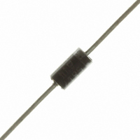
DIODE SCHOTTKY 30V 1A DO-41

1N5818

Manufacturer Part Number
1N5818
Description
DIODE SCHOTTKY 30V 1A DO-41
Manufacturer
STMicroelectronics
Datasheet

Specifications of 1N5818

Voltage - Forward (vf) (max) @ If
500mV @ 1A
Voltage - Dc Reverse (vr) (max)
30V
Current - Average Rectified (io)
1A
Current - Reverse Leakage @ Vr
500µA @ 30V
Diode Type
Schottky
Speed
Fast Recovery =< 500ns, > 200mA (Io)
Mounting Type
Through Hole
Package / Case
DO-204AL, DO-41, Axial
Product
Schottky Diodes
Peak Reverse Voltage
30 V
Forward Continuous Current
1 A
Max Surge Current
25 A
Configuration
Single
Forward Voltage Drop
0.5 V
Maximum Reverse Leakage Current
500 uA
Operating Temperature Range
+ 150 C
Mounting Style
Through Hole
Lead Free Status / RoHS Status
Lead free / RoHS Compliant
Reverse Recovery Time (trr)
-
Capacitance @ Vr, F
-
Lead Free Status / Rohs Status
Lead free / RoHS Compliant
Other names
497-4548-2
497-4548-2
497-4548-3

Available stocks

Company
Part Number
Manufacturer
Quantity
Price
Part Number:
1N5818
Manufacturer:
FS8
Quantity:
10 000
Part Number:
1N5818
Manufacturer:
ST
0
Part Number:
1N5818
Manufacturer:
MIC
Quantity:
20 000
Part Number:
1N5818-5600M
Manufacturer:
MICREL/麦瑞
Quantity:
20 000
Part Number:
1N5818-BP
Manufacturer:
MCC
Quantity:
12 695
Part Number:
1N5818-E
Manufacturer:
LRC/乐山
Quantity:
20 000
Company:
Part Number:
1N5818-E3/54
Quantity:
70 000
Part Number:
1N5818-HE
Manufacturer:
LRC/乐山
Quantity:
20 000
Part Number:
1N5818-T
Manufacturer:
DIO
Quantity:
10 000
Part Number:
1N5818-T
Manufacturer:
Microchip
Quantity:
165
Part Number:
1N5818-TP
Manufacturer:
MCC
Quantity:
3 600
Part Number:
1N5818G
Manufacturer:
ON/安森美
Quantity:
20 000
Part Number:
1N5818RL
Manufacturer:
ST
0
Part Number:
1N5818RLG
Manufacturer:
ON
Quantity:
11 494
Part Number:
1N5818W
Manufacturer:
ST
0
MAIN PRODUCTS CHARACTERISTICS
FEATURES AND BENEFITS
n
n
n
n
n
DESCRIPTION
Axial Power Schottky rectifier suited for Switch
Mode Power Supplies and high frequency DC to
DC converters. Packaged in DO41 these devices
are intended for use in low voltage, high frequency
inverters, free wheeling, polarity protection and
small battery chargers.
ABSOLUTE RATINGS (limiting values)
* :
July 2003 - Ed: 4A
Symbol
I
VERY SMALL CONDUCTION LOSSES
NEGLIGIBLE SWITCHING LOSSES
EXTREMELY FAST SWITCHING
LOW FORWARD VOLTAGE DROP
AVALANCHE CAPABILITY SPECIFIED
V
F(RMS)
P
dV/dt
I
I
F(AV)
T
dPtot
FSM
RRM
ARM
Tj
dTj
stg
V
F
V
I
F(AV)
(max)
®
RRM
Repetitive peak reverse voltage
RMS forward current
Average forward current
Surge non repetitive forward
current
Repetitive peak avalanche
power
Storage temperature range
Maximum operating junction temperature *
Critical rate of rise of reverse voltage
T
j
Rth j
(
1
a
)
thermal runaway condition for a diode on its own heatsink
LOW DROP POWER SCHOTTKY RECTIFIER
Parameter
150°C
0.45 V
40 V
1 A
T
tp = 10 ms
Sinusoidal
tp = 1µs Tj = 25°C
L
= 0.5
= 125°C
1N5817 1N5818 1N5819
1200
20
- 65 to + 150
DO41
10000
Value
1200
150
30
10
25
1
900
1N581x
40
Unit
V/µs
°C
°C
W
V
A
A
A
1/5

Related parts for 1N5818

1N5818 Summary of contents

Page 1

... Critical rate of rise of reverse voltage dPtot thermal runaway condition for a diode on its own heatsink dTj Rth July 2003 - Ed 150°C 0.45 V Parameter T = 125° 0 Sinusoidal tp = 1µ 25°C 1N581x DO41 Value 1N5817 1N5818 1N5819 1200 1200 900 - 150 150 10000 Unit °C °C V/µs 1/5 ...

Page 2

... Parameter Lead length = 10 mm Lead length = 10 mm Tests Conditions Tj = 25° RRM Tj = 100° for 1N5817 / 1N5818 for 1N5819 Fig. 2: Average forward power dissipation versus average forward current (1N5819). PF(av)(W) 0.7 = 0.5 0.6 0 0.4 0.3 0.2 T 0.1 =tp/T tp 0.0 0.0 0.1 0.2 0.3 0.4 0.5 0.6 0.7 0.8 0.9 1.0 1.1 1.2 Fig ...

Page 3

... Fig. 3: Normalized avalanche power derating versus pulse duration ARM p P (1µs) ARM 1 0.1 0.01 t (µs) p 0.001 0.01 0 Fig. 5-1: Non repetitive surge peak forward current versus overload duration (maximum values) (1N5817/1N5818). IM( t(s) =0.5 0 1E-3 1E-2 Fig. 6: Relative variation of thermal impedance junction to ambient versus pulse duration (epoxy printed circuit board, e(Cu)=35mm, recommended pad layout) ...

Page 4

... Fig. 8-1: Reverse leakage current versus reverse voltage applied (typical values) (1N5817/1N5818). IR(mA) 1E+1 Tj=125°C 1N5817 1E+0 Tj=100°C 1E-1 1E-2 Tj=25°C VR(V) 1E Fig. 9-1: Forward voltage drop versus forward current (typical values) (1N5817/1N5818). IFM(A) 10.00 1.00 Tj=100°C Tj=125° ...

Page 5

... No license is granted by implication or otherwise under any patent or patent rights of STMicroelectronics. Specifications mentioned in this publication are subject to change without notice. This publication supersedes and replaces all information previously supplied. ...

Related keywords