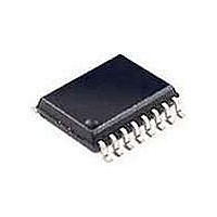
TFA9841J NXP Semiconductors, TFA9841J Datasheet

TFA9841J
Specifications of TFA9841J
Available stocks
Related parts for TFA9841J
TFA9841J Summary of contents
Page 1
... The TFA9841J comes in a 9-pin DIL-bent-SIL (DBS9P) power package. The TFA9841J is pin compatible with the TFA9842J and TFA9843J. The TFA9841J contains a unique protection circuit that is solely based on multiple temperature measurements inside the chip. This gives maximum output power for all supply voltages and load conditions with no unnecessary audio holes. Almost any supply voltage and load impedance combination can be made as long as thermal boundary conditions (external heatsink and ambient temperature) allow it ...
Page 2
... Table 1: Symbol Parameter stb P o THD G v SVRR 5. Ordering information Table 2: Type number TFA9841J DBS9P 6. Block diagram Fig 1. Block diagram. 9397 750 12014 Preliminary data Quick reference data Conditions supply voltage operating no signal quiescent supply current standby supply current output power ...
Page 3
... and C = 220 nF ---------------------------------------------------------------- - – – 220 10 Rev. 01 — 06 February 2004 TFA9841J 1-channel audio amplifi SE TFA9841J MDB796 = 12 Hz © Koninklijke Philips Electronics N.V. 2004. All rights reserved. (1) ( ...
Page 4
... Table 4: Headroom For the average listening level a power dissipation of 2.2 W can be used for a heatsink calculation. 8.3 Mode selection The TFA9841J has three functional modes, which can be selected by applying the proper DC voltage to pin MODE (see Table 5: V MODE 0 to 0 ...
Page 5
... SVRR as function of the frequency. A larger capacitor value on pin SVR improves the ripple rejection behavior at the lower frequencies. 8.5 Built-in protection circuits The TFA9841J contains two types of temperature sensors; one measures local temperatures of the power stage and one measures the global chip temperature local temperature of the power stage of approximately 185 of approximately 150 High impedance of the output is the result ...
Page 6
... V; measured in test circuit MODE CC i Conditions operating MODE on mode mute mode standby mode 0 < V < V 3.5 MODE CC > Rev. 01 — 06 February 2004 TFA9841J 1-channel audio amplifi SE) Min Max 0.3 +26 0.3 +28 0 +150 40 + Value 40 4.0 Figure 11; unless otherwise specified. ...
Page 7
... W; see Figure 7 and o Figure 8 see Figure kHz ripple f = 100 kHz ripple = measured with an input voltage (RMS bandwidth from kHz mV Rev. 01 — 06 February 2004 TFA9841J 1-channel audio amplifi SE) Figure 11; unless otherwise specified. Min Typ Max - 7 6 0.1 0 [1] - 150 - [ [ [ 150 ...
Page 8
... CC L Fig 7. Total harmonic distortion-plus-noise as function of output power. 9397 750 12014 Preliminary data MDB809 (V) THD = 10 %. Fig 6. Output power as function of supply voltage for MCE488 THD ( Fig 8. Total harmonic distortion-plus-noise as Rev. 01 — 06 February 2004 TFA9841J 1-channel audio amplifi SE various SE loads. 10 (%) ...
Page 9
... L Fig 9. Total power dissipation as function of channel output power. 9397 750 12014 Preliminary data MDB799 ( bandpass filter kHz has been applied input short-circuited. Fig 10. Supply voltage ripple rejection as function of Rev. 01 — 06 February 2004 TFA9841J 1-channel audio amplifi SE) 0 SVRR (dB 300 mV (RMS); a ...
Page 10
... Preliminary data 220 nF IN1 CIV 3 STANDBY MODE 7 MUTE SVR 6 TFA9841J GND Rev. 01 — 06 February 2004 TFA9841J 1-channel audio amplifi SE) 100 nF OUT1 2 470 F SHORT-CIRCUIT AND TEMPERATURE V REF PROTECTION V CC 0.5V CC mdb794 © Koninklijke Philips Electronics N.V. 2004. All rights reserved 1000 ...
Page 11
... F CIV IN2 = 60 C (example) amb(max and 150 C (specification) j(max) is the total thermal resistance between the junction and the ambient including = (T T )/P th(tot) j(max) amb(max) D Rev. 01 — 06 February 2004 TFA9841J 1-channel audio amplifi SE TVA TFA9843J 100 nF 1000 F 220 nF 150 F MODE ...
Page 12
... K/W th(tot 40.9 th(h-a) th(tot) th(j-mb) 150 100 External heatsink of 10 K/W; with music signals; T Rev. 01 — 06 February 2004 TFA9841J 1-channel audio amplifi SE) 4.0 = 16.5 K/W. 4.0 = 36.9 K/W. MDB800 ( amb © Koninklijke Philips Electronics N.V. 2004. All rights reserved ...
Page 13
... scale ( 14.7 3 12.4 11.4 3.5 2.54 1.27 5.08 14.3 2 11.0 10.0 REFERENCES JEDEC JEITA Rev. 01 — 06 February 2004 TFA9841J 1-channel audio amplifi SE view B: mounting base side 6.7 4.5 3.4 1.15 17.5 3.8 2.8 4.85 5.5 3.7 3.1 0.85 16.3 3.6 ...
Page 14
... Suitability of through-hole mount IC packages for dipping and wave soldering methods [2] For SDIP packages, the longitudinal axis must be parallel to the transport direction of the printed-circuit board. For PMFP packages hot bar soldering or manual soldering is suitable. Rev. 01 — 06 February 2004 TFA9841J 1-channel audio amplifi SE) Soldering method Dipping Wave [1] suitable ...
Page 15
... Philips Semiconductors 17. Revision history Table 11: Revision history Rev Date CPCN Description 01 20040206 - Preliminary data (9397 750 12014) 9397 750 12014 Preliminary data Rev. 01 — 06 February 2004 TFA9841J 1-channel audio amplifi SE) © Koninklijke Philips Electronics N.V. 2004. All rights reserved ...
Page 16
... Rev. 01 — 06 February 2004 TFA9841J 1-channel audio amplifi SE) Fax: + 24825 © Koninklijke Philips Electronics N.V. 2004. All rights reserved. ...
Page 17
... Publication thereof does not convey nor imply any license under patent- or other industrial or intellectual property rights. Date of release: 06 February 2004 Document order number: 9397 750 12014 TFA9841J 1-channel audio amplifi SE) ...


