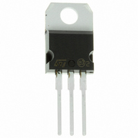
STP2NK60Z STMicroelectronics, STP2NK60Z Datasheet

STP2NK60Z
Specifications of STP2NK60Z
Available stocks
Related parts for STP2NK60Z
STP2NK60Z Summary of contents
Page 1
... I SWITH MODE LOW POWER I SUPPLIES(SMPS) LOW POWER, BALLAST, CFL (COMPACT I FLUORESCENT LAMPS) Table 2: Order Codes Part Number STQ2NK60ZR-AP STP2NK60Z STD2NK60Z-1 STF2NK60Z November 2004 STF2NK60Z - STQ2NK60ZR-AP STP2NK60Z - STD2NK60Z-1 Zener-Protected SuperMESH™ MOSFET Figure 1: Package DS(on) D < 8 Ω 1 < 8 Ω 0 < 8 Ω 1 < ...
Page 2
... STQ2NK60ZR-AP - STP2NK60Z - STF2NK60Z - STD2NK60Z-1 Table 3: Absolute Maximum ratings Symbol V Drain-source Voltage ( Drain-gate Voltage (R DGR V Gate- source Voltage GS I Drain Current (continuous Drain Current (continuous Drain Current (pulsed Total Dissipation at T TOT Derating Factor V Gate source ESD (HBM-C= 100pF, R=1.5kΩ) ESD(G-S) ...
Page 3
... Pulsed: Pulse duration = 300 µs, duty cycle 1.5 %. (2) Pulse width limited by safe operating area. ( defined as a constant equivalent capacitance giving the same charging time as Coss when VDS increases from 0 to 80% VDSS oss eq. STQ2NK60ZR-AP - STP2NK60Z - STF2NK60Z - STD2NK60Z-1 =25°C UNLESS OTHERWISE SPECIFIED) CASE Test Conditions I ...
Page 4
... STQ2NK60ZR-AP - STP2NK60Z - STF2NK60Z - STD2NK60Z-1 Figure 3: Safe Operating Area For TO-220 . Figure 4: Safe Operating Area For IPAK Figure 5: Safe Operating Area For TO-92 4/15 Figure 6: Thermal Impedance For TO-220 Figure 7: Thermal Impedance For IPAK Figure 8: Thermal Impedance For TO-92 ...
Page 5
... Figure 9: Safe Operating Area For TO-220FP Figure 10: Output Characteristics Figure 11: Transconductance STQ2NK60ZR-AP - STP2NK60Z - STF2NK60Z - STD2NK60Z-1 Figure 12: Thermal Impedance For TO-220FP Figure 13: Transfer Characteristics Figure 14: Gate Charge vs Gate-source Voltage 5/15 ...
Page 6
... STQ2NK60ZR-AP - STP2NK60Z - STF2NK60Z - STD2NK60Z-1 Figure 15: Static Drain-source On Resistance Figure 16: Capacitance Variations Figure 17: Normalized Gate Thereshold Volt- age vs Temperature 6/15 Figure 18: Source-Drain Forward Characteris- tics Figure 19: Maximum Avalanche Energy vs Temperature Figure 20: Normalized On Resistance vs Tem- perature ...
Page 7
... Figure 21: Normalized BV DSS STQ2NK60ZR-AP - STP2NK60Z - STF2NK60Z - STD2NK60Z-1 vs Temperature 7/15 ...
Page 8
... STQ2NK60ZR-AP - STP2NK60Z - STF2NK60Z - STD2NK60Z-1 Figure 22: Switching Times Test Circuit For Resistive Load Figure 23: Test Circuit For Inductive Load Switching and Diode Recovery Times 8/15 Figure 24: Gate Charge Test Circuit ...
Page 9
... STQ2NK60ZR-AP - STP2NK60Z - STF2NK60Z - STD2NK60Z-1 TO-92 MECHANICAL DATA mm. DIM. MIN. TYP A 4.32 b 0.36 D 4.45 E 3.30 e 2.41 e1 1.14 L 12.70 R 2.16 S1 0.92 W 0.41 V 5° inch MAX. MIN. TYP. 4.95 0.170 0.51 0.014 4.95 0.175 3.94 0.130 2.67 0.094 1.40 0.044 15.49 0.50 2.41 ...
Page 10
... STQ2NK60ZR-AP - STP2NK60Z - STF2NK60Z - STD2NK60Z-1 DIM. MIN. A 4.4 B 2.5 D 2.5 E 0.45 F 0.75 F1 1.15 F2 1.15 G 4. 28.6 L4 9.8 L5 2 Ø 3 10/15 TO-220FP MECHANICAL DATA mm. TYP MAX. MIN. 4.6 0.173 2.7 0.098 2.75 0.098 0.7 0.017 1 0.030 1.7 0.045 1.7 0.045 5.2 ...
Page 11
... STQ2NK60ZR-AP - STP2NK60Z - STF2NK60Z - STD2NK60Z-1 TO-220 MECHANICAL DATA mm. DIM. MIN. TYP A 4.40 b 0.61 b1 1.15 c 0.49 D 15. 2.40 e1 4.95 F 1.23 H1 6. 3.50 L20 16.40 L30 28.90 øP 3.75 Q 2.65 inch MAX. MIN. TYP. 4.60 0.173 0.88 0.024 1.70 0.045 0.70 0.019 15.75 ...
Page 12
... STQ2NK60ZR-AP - STP2NK60Z - STF2NK60Z - STD2NK60Z-1 DIM. MIN. A 2.2 A1 0.9 A3 0.7 B 0. 0. 6.4 G 4 0.8 L2 12/15 TO-251 (IPAK) MECHANICAL DATA mm TYP. MAX. 2.4 1.1 1.3 0.9 5.4 0.85 0.3 0.95 0.6 0.6 6.2 6.6 4.6 16.3 9.4 1.2 0.8 ...
Page 13
... STQ2NK60ZR-AP - STP2NK60Z - STF2NK60Z - STD2NK60Z-1 DIM. MIN. A1 4. 0.41 P0 12.5 P2 5.65 F1, F2 2.44 delta 17.5 W0 5 18 delta P -1 TO-92 AMMOPACK mm. TYP MAX. 4.95 0.170 3.94 0.130 1.6 2.3 0.56 0.016 12.7 12.9 6.35 7.05 2.54 2. 6.3 9 9.25 0.5 20 ...
Page 14
... STQ2NK60ZR-AP - STP2NK60Z - STF2NK60Z - STD2NK60Z-1 Table 10: Revision History Date Revision 07-Jul-2004 3 11/Nov/2004 4 14/15 Description of Changes The document change from “TARGET” to “COMPLETE” New stylesheet Added TO-220FP ...
Page 15
... Australia - Belgium - Brazil - Canada - China - Czech Republic - Finland - France - Germany - Hong Kong - India - Israel - Italy - Japan - Malaysia - Malta - Morocco - Singapore - Spain - Sweden - Switzerland - United Kingdom - United States of America STQ2NK60ZR-AP - STP2NK60Z - STF2NK60Z - STD2NK60Z-1 All other names are the property of their respective owners © ...


