BUK7515-100A,127 NXP Semiconductors, BUK7515-100A,127 Datasheet
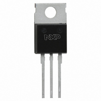
MOSFET N-CH 100V 75A SOT78

BUK7515-100A,127

Manufacturer Part Number
BUK7515-100A,127
Description
MOSFET N-CH 100V 75A SOT78
Manufacturer
NXP Semiconductors
Series
TrenchMOS™r
Datasheets

Specifications of BUK7515-100A,127

Package / Case
TO-220AB-3
Fet Type
MOSFET N-Channel, Metal Oxide
Fet Feature
Standard
Rds On (max) @ Id, Vgs
15 mOhm @ 25A, 10V
Drain To Source Voltage (vdss)
100V
Current - Continuous Drain (id) @ 25° C
75A
Vgs(th) (max) @ Id
4V @ 1mA
Input Capacitance (ciss) @ Vds
6000pF @ 25V
Power - Max
300W
Mounting Type
Through Hole
Minimum Operating Temperature
- 55 C
Configuration
Single
Transistor Polarity
N-Channel
Resistance Drain-source Rds (on)
0.15 Ohm @ 10 V
Drain-source Breakdown Voltage
100 V
Gate-source Breakdown Voltage
+/- 20 V
Continuous Drain Current
75 A
Power Dissipation
300000 mW
Maximum Operating Temperature
+ 175 C
Mounting Style
SMD/SMT
Lead Free Status / RoHS Status
Lead free / RoHS Compliant
Gate Charge (qg) @ Vgs
-
Lead Free Status / Rohs Status
Lead free / RoHS Compliant
Other names
934055409127
BUK7515-100A
BUK7515-100A
Philips Semiconductors
GENERAL DESCRIPTION
N-channel
standard level field-effect power
transistor in a plastic envelope using
’trench’ technology which features
very low on-state resistance. It is
intended for use in automotive and
general
applications.
PINNING - TO220AB
LIMITING VALUES
Limiting values in accordance with the Absolute Maximum System (IEC 134)
THERMAL RESISTANCES
June 2003
TrenchMOS
Standard level FET
SYMBOL
V
V
I
I
I
P
T
SYMBOL
R
R
D
D
DM
PIN
V
stg
tab
DS
DGR
tot
th j-mb
th j-a
1
2
3
GS
, T
j
gate
drain
source
drain
purpose
enhancement
DESCRIPTION
PARAMETER
Drain-source voltage
Drain-gate voltage
Gate-source voltage
Drain current (DC)
Drain current (DC)
Drain current (pulse peak value)
Total power dissipation
Storage & operating temperature
PARAMETER
Thermal resistance junction to
mounting base
Thermal resistance junction to
ambient
transistor
switching
mode
QUICK REFERENCE DATA
PIN CONFIGURATION
SYMBOL
V
I
P
T
R
D
j
DS
tot
DS(ON)
CONDITIONS
-
R
-
T
T
T
T
-
CONDITIONS
-
in free air
mb
mb
mb
mb
GS
tab
PARAMETER
Drain-source voltage
Drain current (DC)
Total power dissipation
Junction temperature
Drain-source on-state
resistance
= 25 ˚C
= 100 ˚C
= 25 ˚C
= 25 ˚C
= 20 k
1 2 3
1
V
GS
= 10 V
SYMBOL
TYP.
MIN.
- 55
60
-
-
-
-
-
-
-
-
g
MAX.
Product specification
BUK7515-100A
100
300
175
75
15
MAX.
MAX.
60.8
100
100
240
300
175
0.5
20
75
-
d
s
Rev 1.200
UNIT
UNIT
K/W
K/W
UNIT
˚C
W
m
V
V
V
A
A
A
˚C
W
V
A

Related parts for BUK7515-100A,127

BUK7515-100A,127 Summary of contents

Page 1

... Junction temperature j R Drain-source on-state DS(ON) resistance V GS PIN CONFIGURATION tab CONDITIONS - ˚ 100 ˚ ˚ ˚ CONDITIONS - in free air 1 Product specification BUK7515-100A MAX. UNIT 100 75 300 175 SYMBOL MIN. MAX. UNIT - 100 - 100 - 60.8 - 240 - 300 - 55 175 TYP. MAX. UNIT - 0 ...

Page 2

... Measured from drain lead 6 mm from package to centre of die Measured from source lead 6 mm from package to source bond pad CONDITIONS -dI /dt = 100 - CONDITIONS ˚ Product specification BUK7515-100A MIN. TYP. MAX. UNIT 100 - - 3 500 100 nA - 12.0 15.0 m ...

Page 3

... ID/A 250 200 150 100 50 120 140 160 180 0 Fig.5. Typical output characteristics ˚C Fig.6. Typical on-state resistance Product specification BUK7515-100A Fig.4. Transient thermal impedance f(t); parameter j-mb 20.0 VGS VDS f(V ); parameter RDS(ON)/mOhm VGS/V = 5.5 6.0 6.5 7.0 8.0 10 ...

Page 4

... June 2003 ˚C. Fig.10. Normalised drain-source on-state resistance 175 1E-01 1E-02 1E-03 1E-04 1E-05 1E- 100 = 25 ˚ Product specification BUK7515-100A Rds(on) normalised to 25degC a 3 2.5 2 1.5 1 0.5 -100 - 100 Tmb / degC / DS(ON) DS(ON)25 ˚ VGS(TO max. 4 typ. 3 min -100 -50 ...

Page 5

... June 2003 Ciss Coss Crss 10 100 , Fig.16. Normalised avalanche energy rating. iss oss rss = MHz 80V VGS 0 80 100 120 DS 25 VGS 0 0.7 0.8 0 Product specification BUK7515-100A WDSS% 120 110 100 100 120 140 Tmb / f(T ); conditions: I DSS VDS T.U.T. ...

Page 6

... Refer to mounting instructions for SOT78 (TO220) envelopes. 3. Epoxy meets UL94 V0 at 1/8". June 2003 10,3 max 3,7 2,8 3,0 13,5 min 1 max (2x) 0,9 max (3x) 2,54 2,54 Fig.19. SOT78 (TO220AB); pin 2 connected to mounting base. 6 Product specification BUK7515-100A 4,5 max 1,3 5,9 min 0,6 2,4 Rev 1.200 15,8 max ...

Page 7

... Philips customers using or selling these products for use in such applications their own risk and agree to fully indemnify Philips for any damages resulting from such improper use or sale. June 2003 7 Product specification BUK7515-100A Rev 1.200 ...

Related keywords