SD2933 STMicroelectronics, SD2933 Datasheet

TRANS RF N-CH HF/VHF/UHF M177

SD2933

Manufacturer Part Number
SD2933
Description
TRANS RF N-CH HF/VHF/UHF M177
Manufacturer
STMicroelectronics
Datasheet

Specifications of SD2933

Transistor Type
N-Channel
Frequency
30MHz
Gain
23.5dB
Voltage - Rated
125V
Current Rating
40A
Current - Test
250mA
Voltage - Test
50V
Power - Output
300W
Package / Case
M177
Application
HF/VHF/UHF
Channel Type
N
Channel Mode
Enhancement
Continuous Drain Current
40A
Drain Source Voltage (max)
125V
Output Power (max)
400W
Power Gain (typ)@vds
23.5dB
Frequency (max)
150MHz
Package Type
Case M-177
Pin Count
4
Forward Transconductance (typ)
10(Min)S
Input Capacitance (typ)@vds
1000@50VpF
Output Capacitance (typ)@vds
372@50VpF
Reverse Capacitance (typ)
29@50VpF
Operating Temp Range
-65C to 200C
Drain Efficiency (typ)
65%
Mounting
Screw
Number Of Elements
1
Power Dissipation (max)
648000mW
Vswr (max)
3(Min)
Screening Level
Military
Lead Free Status / RoHS Status
Lead free / RoHS Compliant
Noise Figure
-
Lead Free Status / Rohs Status
Compliant
Other names
497-5469
SD2933

Available stocks

Company
Part Number
Manufacturer
Quantity
Price
Part Number:
SD2933
Manufacturer:
ST
0
Part Number:
SD2933
Manufacturer:
ST
Quantity:
20 000
Part Number:
SD2933-02
Manufacturer:
ST
0
Part Number:
SD2933-03W
Manufacturer:
ST
0
Part Number:
SD2933W
Manufacturer:
ST
0
Part Number:
SD2933W
0
• GOLD METALLIZATION
• EXCELLENT THERMAL STABILITY
• COMMON SOURCE CONFIGURATION
• P
• THERMALLY ENHANCED PACKAGING FOR
DESCRIPTION
The SD2933 is a gold metallized N-Channel MOS
field-effect RF power transistor. It is intended for
use in 50 V dc large signal applications up 150
MHz. It’s special low thermal resistance package,
makes it ideal for ISM applications where reliability
and ruggedness are critical factors.
ORDER CODES
ABSOLUTE MAXIMUM RATINGS (T
(1) Repetitive rating: Pulse width limited by maximum junction temperature
THERMAL DATA
July 2004
30 MHz
LOWER JUNCTION TEMPERATURES
V
Symbol
Repetitive avalanche causes additional power losses that can be calculated as: P
E
R
(BR)DSS
OUT
P
V
T
V
E
AR
th(j-c)
DISS
DGR
STG
I
T
GS
Order Codes
D
AS
j
(1)
= 300 W MIN. WITH 20 dB GAIN @
SD2933
Drain Source Voltage
Drain-Gate Voltage (R
Gate-Source Volatge
Drain Current
Power Dissipation
Max. Operating Junction Temperature
Avalanche Energy, Single Pulse (I
Avalanche Energy, Repetitive
Storage Temperature
Junction -Case Thermal Resistance
Marking
SD2933
GS
Parameter
= 1M )
CASE
HF/VHF/UHF N-CHANNEL MOSFETs
= 25
D
= 60 A)
°
C)
Package
RF POWER TRANSISTORS
M177
1. Drain
2. Source
3. Gate
AV
= E
AR
PIN CONNECTION
* f
epoxy sealed
3
4
-65 to +150
M177
Value
1500
0.27
125
125
±20
648
200
40
50
Plastic Tray
Packaging
1
2
SD2933
REV. 9
4. Source
5. Source
5
°C/W
Unit
mJ
mJ
°C
°C
W
V
V
V
A
1/8

Related parts for SD2933

SD2933 Summary of contents

Page 1

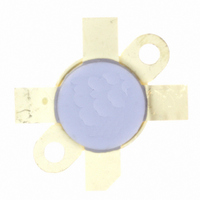
... MHz • THERMALLY ENHANCED PACKAGING FOR LOWER JUNCTION TEMPERATURES DESCRIPTION The SD2933 is a gold metallized N-Channel MOS field-effect RF power transistor intended for use large signal applications up 150 MHz. It’s special low thermal resistance package, makes it ideal for ISM applications where reliability and ruggedness are critical factors ...

Page 2

... SD2933 ELECTRICAL SPECIFICATION (T STATIC Symbol (BR)DSS DSS GSS GS( DS(ON ISS OSS RSS GS G sorts for each unit FS DYNAMIC Symbol 250 mA OUT 250 250 250 mA P Load DD DQ Mismatch All Phase Angles D Typical Input Impedance G Zin S 2 ° CASE Test Conditions I = 200 mA ...

Page 3

... Tc, CASE TEMPERATURE (ºC) Drain Current vs. Gate Voltage 15 Ciss 10 Coss 5 Crss Maximum Thermal Resistance vs. Case Temperature Id=. 100 Vdd=10V 1.5 2 2.5 3 Vgs, Gate-Source Voltage (V) 0.33 0.32 0.31 0.3 0.29 0.28 0.27 0. Tc, CASE TEMPERATURE (°C) SD2933 3 3/8 ...

Page 4

... SD2933 TYPICAL PERFORMANCE Output Power vs. Input Power 500 400 300 200 100 0 0 0.3 0.6 0.9 1.2 1.5 Pin, Input Power ( W ) Power Gain vs. Output Power 100 200 Pout, Output Power (W) Output Power vs. Supply Voltage 450 400 MHz Pin = 2.6 W Idq = 250 mA ...

Page 5

... TURN AIR-WOUND 16 AWG ID = 0.219 [5.56] POLY-COATED MAGNET WIRE L2 1 3/4 TURN AIR-WOUND 12 AWG ID = 0.250 [6.34] BUS BAR WIRE RFC1,RFC2 3 TURNS 14 AWG WIRE THROUGH FAIR RITE TOROID FB1 SURFACE MOUNT EMI SHIELD BEAD FB2 TOROID PCB ULTRALAM 2000. 0.030” THK 2.55 BOTH SIDES SD2933 REF. 1008706A 5/8 ...

Page 6

... SD2933 30 MHz Test Circuit Photomaster 30 MHz Test Circuit 6/8 6.4 inches ...

Page 7

... TYP. MAX 5.97 0.225 6.96 0.265 22.10 0.860 28.96 1.130 14.10 0.545 0.18 0.003 2.74 0.098 4.32 0.150 7.11 28.45 1.080 16.13 0.625 Inch MIN. TYP. MAX 0.235 0.275 0.870 1.140 0.555 0.007 0.108 0.170 0.280 1.120 0.635 1011012D SD2933 7/8 ...

Page 8

... SD2933 Information furnished is believed to be accurate and reliable. However, STMicroelectronics assumes no responsibility for the consequences of use of such information nor for any infringement of patents or other rights of third parties which may result from its use. No license is granted by implication or otherwise under any patent or patent rights of STMicroelectronics. Specifications mentioned in this publication are subject to change without notice ...

Related keywords