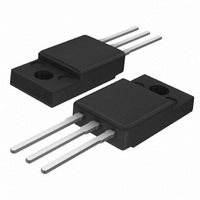
BT151X-500C,127 NXP Semiconductors, BT151X-500C,127 Datasheet - Page 2

BT151X-500C,127
Manufacturer Part Number
BT151X-500C,127
Description
THYRISTOR 500V 12A TO-220F
Manufacturer
NXP Semiconductors
Datasheet
1.BT151X-650C127.pdf
(6 pages)
Specifications of BT151X-500C,127
Package / Case
TO-220-3 Full Pack
Scr Type
Standard Recovery
Voltage - Off State
500V
Voltage - Gate Trigger (vgt) (max)
1.5V
Voltage - On State (vtm) (max)
1.75V
Current - On State (it (av)) (max)
7.5A
Current - On State (it (rms)) (max)
12A
Current - Gate Trigger (igt) (max)
15mA
Current - Hold (ih) (max)
20mA
Current - Off State (max)
500µA
Current - Non Rep. Surge 50, 60hz (itsm)
100A, 110A
Operating Temperature
-40°C ~ 125°C
Mounting Type
Through Hole
Current - On State (it (rms) (max)
12A
Breakover Current Ibo Max
110 A
Rated Repetitive Off-state Voltage Vdrm
500 V
Off-state Leakage Current @ Vdrm Idrm
0.5 mA
Forward Voltage Drop
1.75 V
Gate Trigger Voltage (vgt)
1.5 V
Maximum Gate Peak Inverse Voltage
5 V
Gate Trigger Current (igt)
15 mA
Holding Current (ih Max)
20 mA
Mounting Style
SMD/SMT
Lead Free Status / RoHS Status
Lead free / RoHS Compliant
Other names
934058505127
BT151X-500C
BT151X-500C
BT151X-500C
BT151X-500C
Philips Semiconductors
ISOLATION LIMITING VALUE & CHARACTERISTIC
T
THERMAL RESISTANCES
STATIC CHARACTERISTICS
T
DYNAMIC CHARACTERISTICS
T
April 2004
Thyristors
hs
SYMBOL
V
C
SYMBOL PARAMETER
R
R
j
SYMBOL PARAMETER
I
I
I
V
V
I
j
SYMBOL PARAMETER
dV
t
t
GT
L
H
D
gt
q
= 25 ˚C unless otherwise stated
= 25 ˚C unless otherwise stated
isol
T
GT
isol
th j-hs
th j-a
, I
= 25 ˚C unless otherwise specified
D
R
/dt
Thermal resistance
junction to heatsink
Thermal resistance
junction to ambient
Gate trigger current
Latching current
Holding current
On-state voltage
Gate trigger voltage
Off-state leakage current
Critical rate of rise of
off-state voltage
Gate controlled turn-on
time
Circuit commutated
turn-off time
PARAMETER
R.M.S. isolation voltage from all f = 50-60 Hz; sinusoidal
three terminals to external
heatsink
Capacitance from pin 2 to
external heatsink
CONDITIONS
with heatsink compound
without heatsink compound
in free air
CONDITIONS
V
V
V
I
V
V
V
CONDITIONS
V
exponential waveform
I
dI
V
I
dV
T
TM
TM
D
D
D
D
D
D
DM
D
G
= 23 A
D
/dt = 5 A/ s
= 12 V; I
= 12 V; I
= 12 V; I
= 12 V; I
= V
= V
= 40 A; V
= 67% V
= 20 A; V
/dt = 50 V/ s; R
= 67% V
CONDITIONS
waveform;
R.H.
f = 1 MHz
DRM(max)
DRM(max)
T
GT
GT
T
DRM(max)
D
R
DRM(max)
= 0.1 A
= 0.1 A
; I
; V
65% ; clean and dustfree
= 0.1 A
= 0.1 A
= V
= 25 V; dI
T
R
2
= 0.1 A; T
= V
DRM(max)
; T
; T
GK
RRM(max)
j
= 125 ˚C;
j
= 100
Gate open circuit
= 125 ˚C;
TM
; I
/dt = 30 A/ s;
G
j
= 125 ˚C
; T
R
= 0.1 A;
GK
j
= 125 ˚C
= 100
MIN.
MIN.
MIN.
MIN.
0.25
200
50
-
-
-
-
-
-
-
-
-
-
-
-
-
BT151X series C
TYP.
TYP.
TYP.
TYP.
1000
1.44
130
10
0.6
0.4
0.1
55
10
70
-
2
7
2
-
-
Product specification
MAX.
2500
MAX.
MAX.
MAX.
1.75
4.5
6.5
1.5
0.5
15
40
20
-
-
-
-
-
-
-
Rev 1.000
UNIT
UNIT
UNIT
UNIT
V/ s
V/ s
K/W
K/W
K/W
mA
mA
mA
mA
pF
V
V
V
V
s
s


