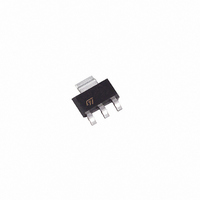
STN790A STMicroelectronics, STN790A Datasheet

STN790A
Specifications of STN790A
Available stocks
Related parts for STN790A
STN790A Summary of contents
Page 1
... Island” layout. The resulting transistor shows exceptional high gain performance coupled with very low saturation voltage. Table 1. Device summary Order code Marking STN790A N790A June 2008 4 SOT-223 Figure 1. Internal schematic diagram Package SOT-223 Rev 4 STN790A Packaging Tape and reel 1/9 www.st.com 9 ...
Page 2
... Storage temperature stg T Max. operating junction temperature J Table 3. Thermal data Symbol R Thermal resistance junction-ambient thj-amb 1. Device mounted on PCB area 2/9 Parameter = Ω < °C amb Parameter (1) __max 2 . STN790A Value Unit -40 V - 1.6 W -65 to 150 °C 150 °C Value Unit 78 °C/W ...
Page 3
... STN790A 2 Electrical characteristics ( °C unless otherwise specified) case Table 4. Electrical characteristics Symbol Collector cut-off current I CBO ( Emitter cut-off current I EBO ( Collector-emitter (1) breakdown voltage V (BR)CEO ( Collector-emitter (1) breakdown voltage V (BR)CER (R BE Collector-base breakdown voltage V (BR)CBO ( Emitter-base breakdown V (BR)EBO voltage (I Collector-emitter (1) V CE(sat) saturation voltage ...
Page 4
... Electrical characteristics (curves) Figure 2. DC current gain Figure 4. Collector-emitter saturation voltage 4/9 Parameter Test conditions MHz - see Figure 8 Figure 3. Figure 5. Min. Typ. Max 100 V = -20 V 180 220 CC 160 210 250 300 80 100 DC current gain Base-emitter saturation voltage STN790A Unit MHz ...
Page 5
... STN790A Figure 6. Switching time resistive load Figure 7. 2.2 Test circuit Figure 8. Resistive load switching test circuit 1) Fast electronic switch 2) Non-inductive resistor Electrical characteristics Switching time resistive load 5/9 ...
Page 6
... These packages have a Lead-free second level interconnect. The category of second level interconnect is marked on the package and on the inner box label, in compliance with JEDEC Standard JESD97. The maximum ratings related to soldering conditions are also marked on the inner box label. ECOPACK trademark. ECOPACK specifications are available at: 6/9 www.st.com STN790A ...
Page 7
... STN790A DIM SOT-223 mechanical data mm. min. typ 0.02 0.60 0.70 2.90 3.00 0.24 0.26 6.30 6.50 2.30 4.60 3.30 3.50 6.70 7.00 Package mechanical data max. 1.80 0.1 0.85 3.15 0.35 6.70 3.70 7. 0046067_L 7/9 ...
Page 8
... Revision history 4 Revision history Table 5. Document revision history Date 24-Mar-2006 26-Jun-2008 8/9 Revision 3 Updated to new template 4 Updated SOT-223 mechanical data. STN790A Changes ...
Page 9
... STN790A Information in this document is provided solely in connection with ST products. STMicroelectronics NV and its subsidiaries (“ST”) reserve the right to make changes, corrections, modifications or improvements, to this document, and the products and services described herein at any time, without notice. All ST products are sold pursuant to ST’s terms and conditions of sale. ...


