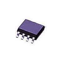
TJA1020TD NXP Semiconductors, TJA1020TD Datasheet - Page 5

TJA1020TD
Manufacturer Part Number
TJA1020TD
Description
RF Transceiver LIN TRANSCEIVER
Manufacturer
NXP Semiconductors
Datasheet
1.TJA1020TD.pdf
(22 pages)
Specifications of TJA1020TD
Number Of Receivers
4
Number Of Transmitters
3
Operating Supply Voltage
5 V to 27 V
Maximum Operating Temperature
+ 150 C
Mounting Style
SMD/SMT
Package / Case
SO-8
Maximum Data Rate
0.02 MBd
Maximum Supply Current
8 mA
Minimum Operating Temperature
- 40 C
Lead Free Status / RoHS Status
Lead free / RoHS Compliant
Other names
TJA1020T/N1,112
Philips Semiconductors
Table 1 Operating modes
Notes
1. The standby mode is entered automatically upon any local or remote wake-up event during sleep mode. Pin INH and
2. The internal wake-up source flag (set if a local wake-up did occur and fed to pin TXD) will be reset when entering
3. The wake-up interrupt (on pin RXD) is released when entering normal slope or low slope mode (NSLP goes HIGH).
4. The normal slope mode is entered during a positive edge on NSLP while pin TXD is already set HIGH. In the event
5. The low slope mode is entered during the positive edge on NSLP while pin TXD is already pulled LOW.
Sleep mode
This mode is the most power saving mode of the TJA1020
and the default state after power-up (first battery supply).
Despite its extreme low current consumption, the TJA1020
can still be waken up remotely via pin LIN, or waken up
locally via pin NWAKE, or activated directly via pin NSLP.
Filters at the inputs of the receiver (LIN), of pin NWAKE
and of pin NSLP are preventing unwanted wake-up events
due to automotive transients or EMI. All wake-up events
have to be maintained for a certain time period (t
t
The sleep mode is initiated by a falling edge on the pin
NSLP while TXD is already set HIGH. After a filter time
continuously driven sleep command (pin NSLP = LOW),
pin INH becomes floating.
In sleep mode the internal slave termination between
pins LIN and BAT is disabled to minimize the power
dissipation in case pin LIN is short-circuited to ground.
Only a weak pull-up between pins LIN and BAT is present.
2004 Jan 13
NWAKE
Sleep
Standby
Normal
slope
mode
Low slope
mode
LIN transceiver
MODE
the 30 k termination resistor at pin LIN are switched on.
normal slope or low slope mode (NSLP goes HIGH).
of a short-circuit to ground on pin TXD, the transmitter will be disabled.
and t
(1)
gotonorm
NSLP
0
0
1
1
).
weak pull-down
weak pull-down if
remote wake-up;
strong pull-down if
local wake-up;
note 2
weak pull-down
weak pull-down
TXD (OUTPUT)
floating
LOW; note 3
HIGH:
recessive state
LOW:
dominant state
HIGH:
recessive state
LOW:
dominant state
RXD
BUS
,
5
floating off
HIGH
HIGH
HIGH
The sleep mode can be activated independently from the
actual level on pin LIN or NWAKE. So it is guaranteed that
the lowest power consumption is achievable even in case
of a continuous dominant level on pin LIN or a continuous
LOW on pin NWAKE.
Standby mode
The standby mode is entered automatically whenever a
local or remote wake-up occurs while the TJA1020 is in its
sleep mode. These wake-up events activate pin INH and
enable the slave termination resistor at the pin LIN. As a
result of the HIGH condition on pin INH the voltage
regulator and the microcontroller can be activated.
The standby mode is signalled by a LOW level on pin RXD
which can be used as an interrupt for the microcontroller.
In the standby mode (pin NSLP is still LOW), the condition
of pin TXD (weak pull-down or strong pull-down) indicates
the wake-up source: weak pull-down for a remote wake-up
request and strong pull-down for a local wake-up request.
INH
off
normal slope
mode
low slope mode
TRANSMITTER
no wake-up request detected
wake-up request detected; in
this mode the microcontroller
can read the wake-up source:
remote or local wake-up
notes 2, 3 and 4
notes 2, 3 and 5
REMARKS
Product specification
TJA1020


