HD1750FX STMicroelectronics, HD1750FX Datasheet
HD1750FX
Specifications of HD1750FX
Available stocks


Related parts for HD1750FX


HD1750FX Summary of contents
Page 1
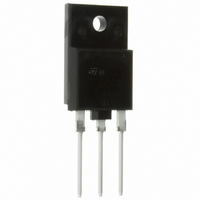
... High-Definition CRT displays. The new HD product series show improved silicon efficiency bringing updated performance to the Horizontal Deflection stage. Table 1: Order Codes Part Number HD1750FX December 2005 Figure 1: Package Figure 2: Internal Schematic Diagram Marking Package HD1750FX ISOWATT218FX HD1750FX ISOWATT218FX Packaging TUBE Rev. 2 1/8 ...
Page 2
... HD1750FX Table 2: Absolute Maximum Ratings Symbol V Collector-Emitter Voltage (V CES V Collector-Emitter Voltage (I CEO V Emitter-Base Voltage (I EBO I Collector Current C I Collector Peak Current ( Base Current B I Base Peak Current ( Total Dissipation at T tot Insulation Withstand Voltage (RMS) from All Three Leads to V ins ...
Page 3
... Figure 3: Safe Operating Area Figure 4: Output Chatacterisctics Figure 5: DC Current Gain Figure 6: Derating Curve Figure 7: Reverse Biased SOA Figure 8: DC Current Gain HD1750FX 3/8 ...
Page 4
... HD1750FX Figure 9: Collector-Emitter Saturation Voltage Figure 10: Power Losses Figure 11: Inductive Load Switching Time 4/8 Figure 12: Base-Emitter Saturation Voltage Figure 13: Power Losses Figure 14: Inductive Load Switching Time ...
Page 5
... Figure 15: Power Losses and Inductive Load Switching Test Circuit Figure 16: Reverse Biased Safe Operating Area Test Circuit HD1750FX 5/8 ...
Page 6
... HD1750FX ISOWATT218FX MECHANICAL DATA DIM. MIN. A 5.30 C 2.80 D 3.10 D1 1.80 E 0.80 F 0.65 F2 1.80 G 10. 15. 22.80 L3 26.30 L4 43.20 L5 4.30 L6 24.30 L7 14.60 N 1.80 R 3.80 Dia 3.40 6/8 mm. TYP 5.45 9 MAX. 5.70 3.20 3.50 2.20 1.10 0.95 2.20 11.50 15.70 10.20 23.20 26.70 44.40 4 ...
Page 7
... Figure 5: Revision History Release Date Version 30-May-2005 1 19-Dec-2005 2 Change Designator Initial Release. New h value in table 4 FE HD1750FX 7/8 ...
Page 8
... HD1750FX Information furnished is believed to be accurate and reliable. However, STMicroelectronics assumes no responsibility for the consequences of use of such information nor for any infringement of patents or other rights of third parties which may result from its use. No license is granted by implication or otherwise under any patent or patent rights of STMicroelectronics. Specifications mentioned in this publication are subject to change without notice ...