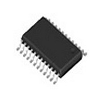
LMX2354TM National Semiconductor, LMX2354TM Datasheet - Page 12

LMX2354TM
Manufacturer Part Number
LMX2354TM
Description
34C6468
Manufacturer
National Semiconductor
Datasheet
1.LMX2354TM.pdf
(23 pages)
Specifications of LMX2354TM
Number Of Elements
2
Supply Current
8.5mA
Pll Input Freq (min)
10MHz
Pll Input Freq (max)
2.5GHz
Operating Supply Voltage (typ)
3V
Operating Temp Range
-40C to 85C
Package Type
TSSOP
Operating Supply Voltage (min)
2.7V
Operating Supply Voltage (max)
5.5V
Operating Temperature Classification
Industrial
Pin Count
24
Pll Type
Frequency Synthesis
Frequency
2.5GHz
Supply Voltage Range
2.7V To 5.5V
Digital Ic Case Style
TSSOP
No. Of Pins
24
Operating Temperature Range
-40°C To +85°C
Rohs Compliant
No
Lead Free Status / RoHS Status
Not Compliant
Available stocks
Company
Part Number
Manufacturer
Quantity
Price
Company:
Part Number:
LMX2354TMA
Manufacturer:
AMI
Quantity:
6 226
Part Number:
LMX2354TMA
Manufacturer:
NS/国半
Quantity:
20 000
www.national.com
OSC
Low modulus prescale (Note 7)
RF Prescaler
Fractional Engine
Functional Description
1.8 Fo/LD MULTIFUNCTION OUTPUT
The Fo/LD output pin can deliver several internal functions
including analog/digital lock detects, and counter outputs.
See programming description 4.1.5 for more details.
1.8.1 Lock Detect
A digital filtered lock detect function is included with each
phase detector through an internal digital filter to produce a
logic level output available on the Fo/LD output pin if se-
lected. The lock detect output is high when the error between
the phase detector inputs is less than 15 ns for 5 consecutive
comparison cycles. The lock detect output is low when the
error between the phase detector outputs is more than 30 ns
for one comparison cycle. An analog lock detect signal is
also selectable. The lock detect output is always low when
the PLL is in power down mode. See programming descrip-
tions 4.1.5, 5.6–5.8 for more details.
1.9 POWER CONTROL
Each PLL is individually power controlled by device enable
pins or MICROWIRE power down bits. The enable pins
override the power down bits except for the V2_EN bit . The
2.0 Major Differences between the LMX2354 and the LMX2350/52
Note 7: If the LMX2354 is replacing a LMX2350/52 in a design, and you are using the lower modulus prescale value (16/17 on the LMX2350 changes to 8/9/12/13
on the LMX2354), the unused prescaler bit of the LMX2350/52 needs to shift down one bit from N
IF
Supports resonator mode.
5-bit A counter, so if 16/17 prescale, bit-5 is
the unused place holder.
LMX2350 — 32/33 or 16/17
LMX2352 — 16/17 or 8/9
Standard. Fractional Compensation cannot
be turned off.
(Continued)
LMX2350/52
12
RF_EN pin controls the RF PLL; IF_EN pin controls the IF
PLL. When both pins are high, the power down bits deter-
mine the state of power control (see programming descrip-
tion 5.2.1.2). Activation of any PLL power down mode results
in the disabling of the respective N counter and de-biasing of
its respective fin input (to a high impedance state). The R
counter functionality also becomes disabled when the power
down bit is activated. The reference oscillator block powers
down and the OSC
when both RF and IF enable pins or power down bit’s are
asserted, unless the V2_EN bit (RF_R[22]) is high . Power
down forces the respective charge pump and phase com-
parator logic to a TRI-STATE condition. A power down
counter reset function resets both N and R counters. Upon
powering up the N counter resumes counting in “close”
alignment with the R counter (The maximum error is one
prescaler cycle). The MICROWIRE control register remains
active and capable of loading and latching in data during all
of the power down modes.
<
9
>
to N
Does not support resonator mode.
4-bit A/B counters, so if 8/9/12/13, bit-4 is
the unused place holder.
LMX2354 — 16/17/20/21 or 8/9/12/13
Similar structure to the LMX2350/52, but with
some modifications for improved phase noise
and spurs. Fractional Compensation can be
turned off.
<
IF
8
>
pin reverts to a high impedance state
.
LMX2354


